Section 1.1 Paper I
Problem 1.1.1. Q1. Reading a Vernier Caliper.
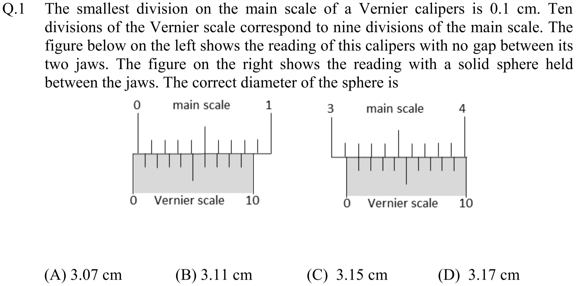
Must account for error properly.
(C).
The figure on the left gives the zero reading.
Reading for the diameter from the figure on the right
Now, we subtract the zero reading to get the actual diamter.
Hence (C).
Problem 1.1.2. Q2. First Law of Thermodynamics.
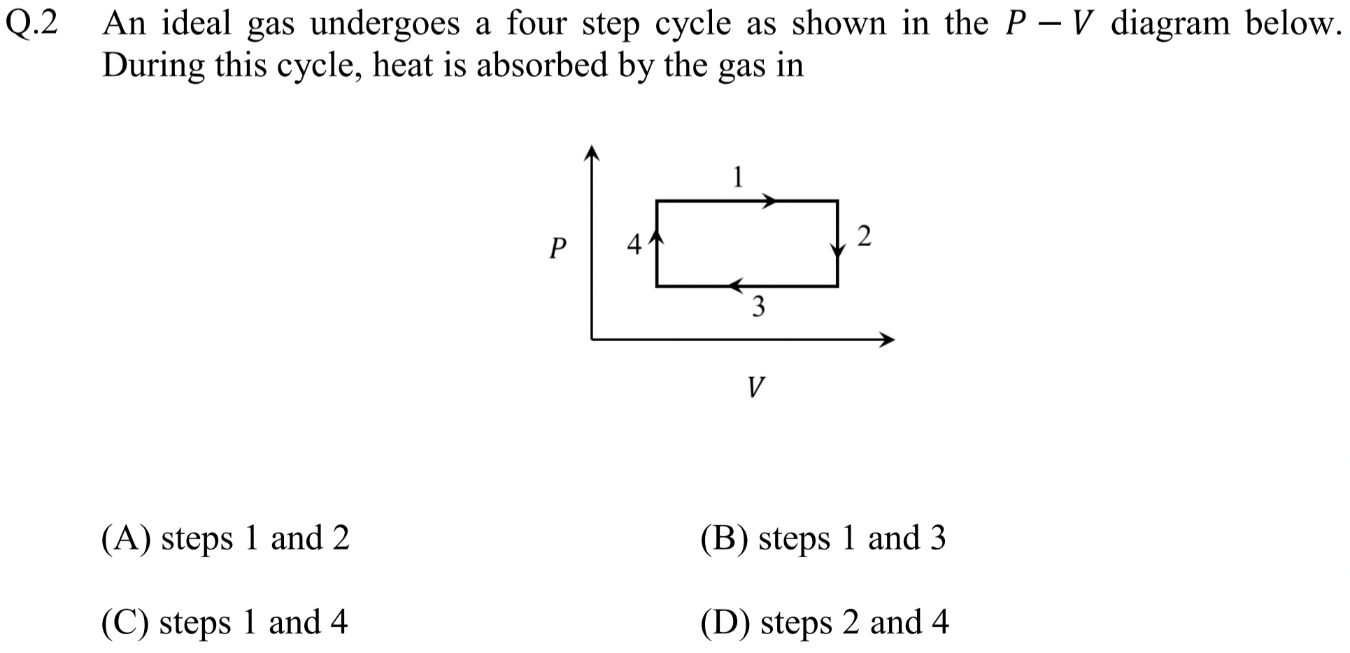
Use \(U=\frac{3}{2}nRT = \frac{3}{2}pV\) for internal energy and first law \(U_2 - U_1 = Q_\text{in} - \int_1^2 pdV\) to find sign of \(Q_\text{in}\) for each step.
(C).
From first law of thermodynamics for a gas process from state 1 to state 2, we have
where minus sign in the work integral takes care of energy loss by the gas in expansion. For internal energy of an (monatomic - not given in the problem) ideal gas we have the following for internal energy in a state \((n, p, V, T)\text{:}\)
Now, we look at each process with notation for states as shown in Figure 1.1.3. States correspond to \((n,p,V,T)\) at the corners of the diagram are labeled with subscripts 1, 2, 3, 4.
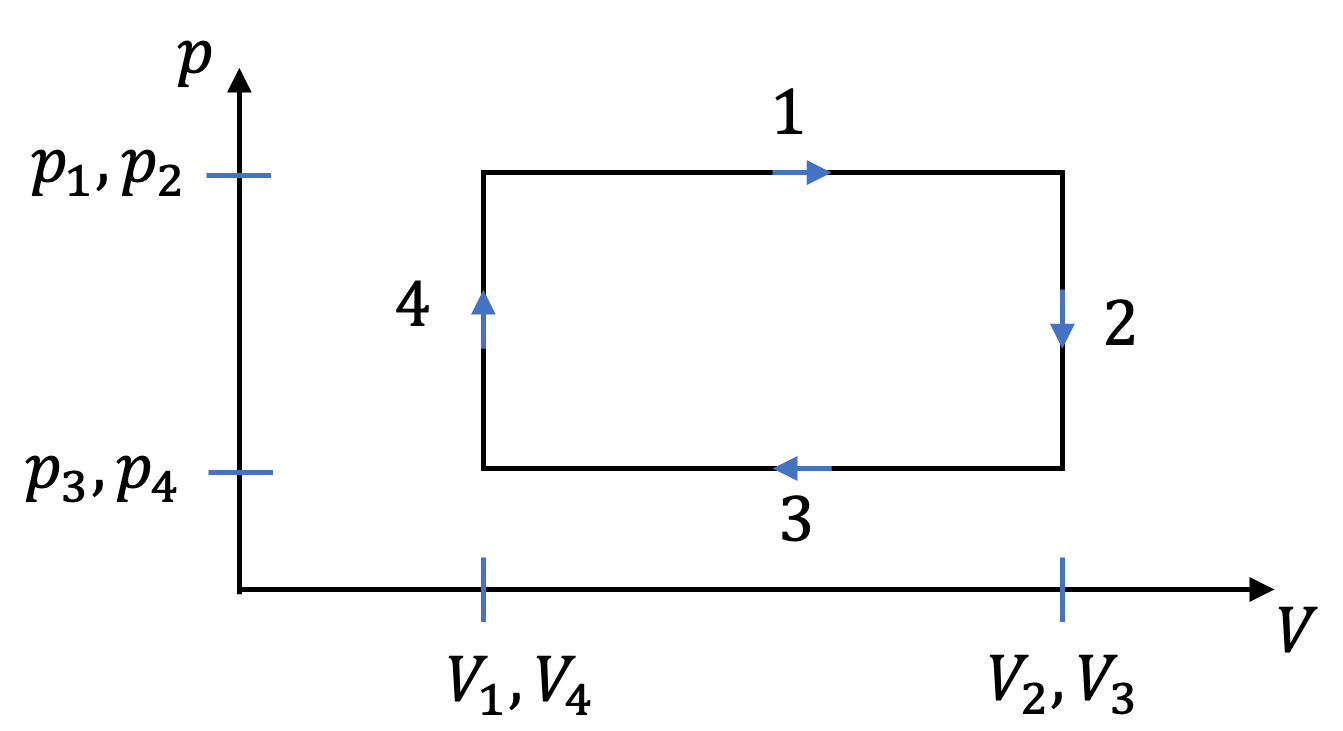
Process (1):
Therefore,
So, (1) has heat going into the system.
Process (2):
Therefore,
So, (2) has heat going out of the system.
Process (3):
Therefore,
So, (3) has heat going out of the system.
Process (4):
Therefore,
So, (4) has heat going into the system.
Hence, answer is (1) and (4). That would be (C).
Problem 1.1.4. Q3. Lens Maker's Equation.
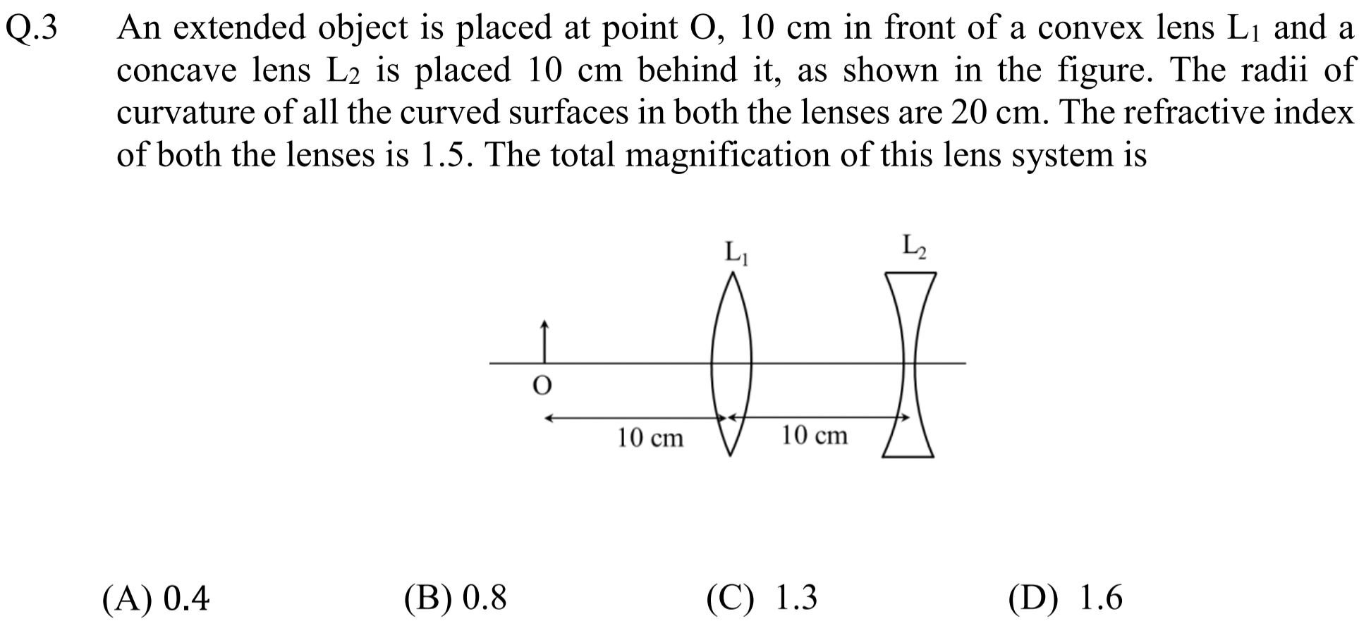
You need to recall lens maker's formula to get focal lengths of the lenses. For power of a lens it is
Work one lens at a time, using the image from first lens as object for the second lens.
(B).
For biconvex lens \(R_1\gt 0\) and \(R_2\lt 0\text{.}\) Therefore,
For biconcave lens \(R_1\lt 0\) and \(R_2\gt 0\text{.}\) Therefore,
To find the final image, we work one lens at a time. Working with first lens, we find the image \(I_1\) from this lens will be at \(q_1\) give by
That is \(q_1 = -20\text{ cm}\text{.}\) Since it is negative, image is to the left of this lens. The magnification by this lens will be
Now, to work with the second lens, image \(I_1\) serves as object to the second lens. Hence, object distance will be
Therefore, final image \(I_2\) will form at \(q_2\) givem by
Therefore, \(q_2 = -12\text{ cm}\text{,}\) i.e., \(12\text{ cm}\) to the left (since negative) of second lems. Magnification by second lens will be
Hence, net magnification is
This is (B). The image has same oriantation as the original object and is \(80\%\) as tall.
Problem 1.1.5. Q4. Probability and Half Life.
Use nuclear decay law, number \(N\) remaining after time \(t\) is \(N = N_0\,e^{-\lambda t}\text{.}\)
(D).
Let \(N(t)\) is the number of undecayed nuclei that ramain in the sample after time \(t\text{.}\) From the nuclear decay law
we immediately get
We can write \(\lambda\) in terms of half life \(t_\text{1/2}\) by noting the condition for \(t= t_\text{1/2}\text{.}\)
Hence,
Thus, we can write the decay law also as (you could start from this formula if you remember it.)
Thus, starting with \(1000\) active nuclei, after one hour we will have remaining (no calculator required!):
Thus, number of decays are
Now, \(60\%\) of them are \(\alpha\)-decays. Hence,
This is (D).
Problem 1.1.6. Q5 and Q6. Projectile Motion and Conservation of Momentum.
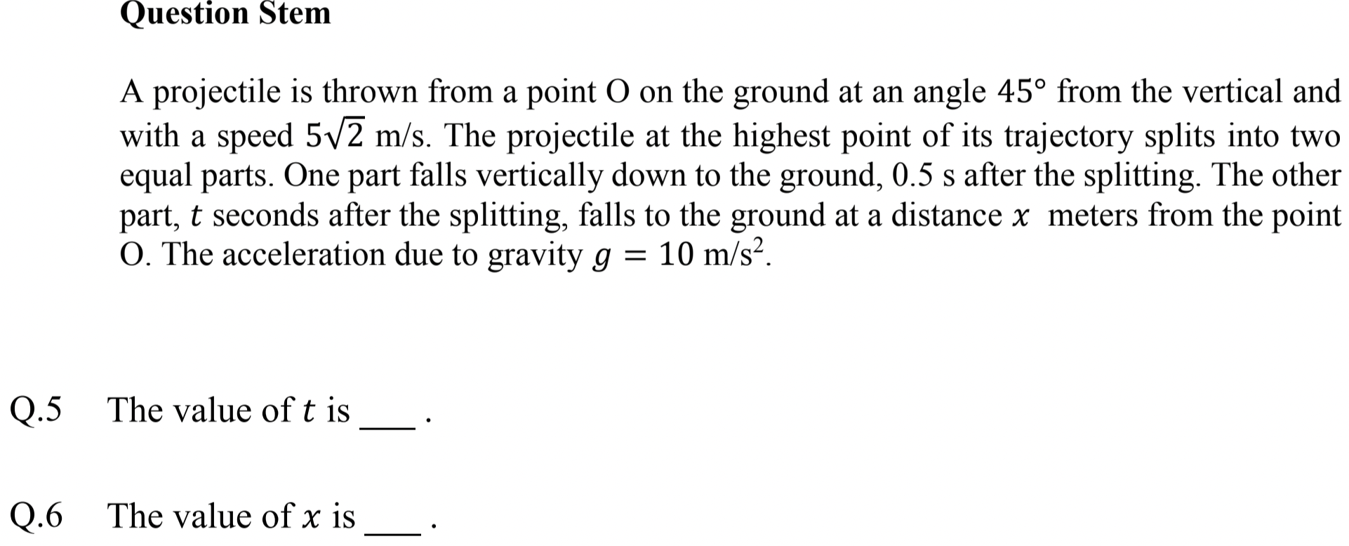
You need to analyze four processes. At the splitting point, implement momentum conservation.
Q5: \(0.5\text{ sec}\text{,}\) Q6: \(7.5\text{ m}\text{.}\)
Strategy. Figure 1.1.7 shows the full extent of this problem. We have four processes (1) projectile motion O-to-A, (2) momentum conservation at A, (3) one-dimensional motion A-to-B, and (4) projectile motion A-to-C.
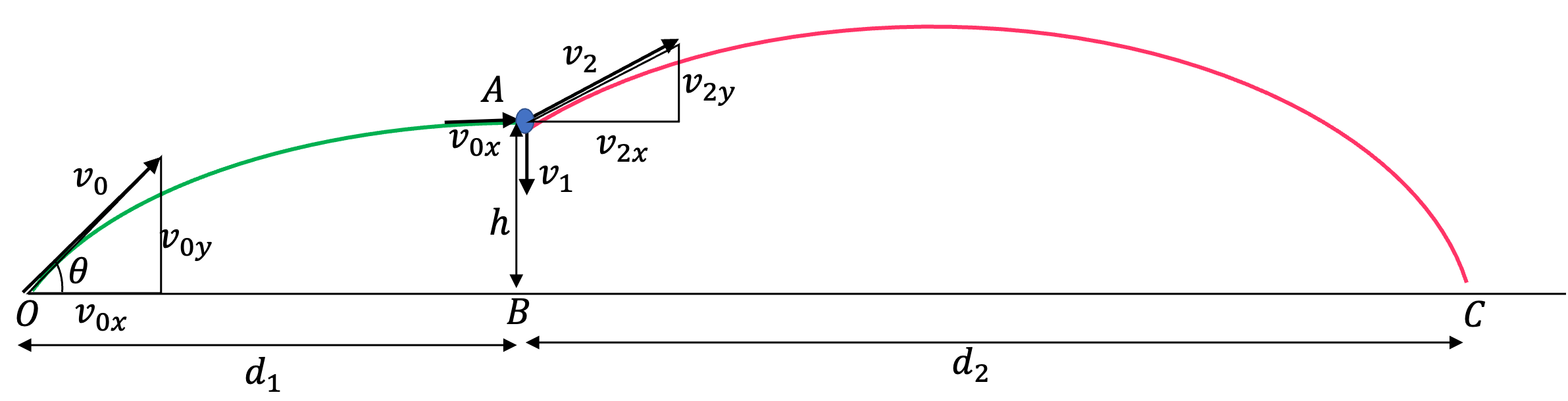
(1) Projectile motion O-to-A:
Let us denote the time taken by \(\Delta t = t_0\text{.}\) Since \(\theta=45^\circ\text{,}\) we have
From these, we get
and
(2) Momentum conservation at A:
We implement momentum conservation at A for horizontal and vertical components as shown in Figure 1.1.8.
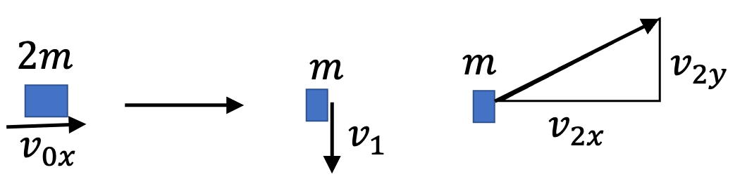
Upon using numerical values, we get
We will get value of \(v_1\) from analysis of A-to-B motion, which we do next.
(3) One-dimensional motion A-to-B:
Here, initial velocity has magnitude \(v_1\) and direction down and acceleration is \(g\) pointed down. It covers a distance \(h=\frac{5}{4}\text{ m}\) found from O-to-A motion in time \(t_1=\frac{1}{2}\text{ sec}\text{.}\) Therefore,
Therefore,
Hence, \(v_1=0\text{.}\) Using this in second equation in (1.1.2) give
(4) Projectile motion A-to-C:
Here, we have \(v_{2x}=10\text{,}\) \(v_{2y}=0\text{,}\) \(h=5/4\text{.}\) The time of flight is given by symbol \(t\) in the problem. Therefore,
Therefore, answer to Q5 is
The horizontal distance from the point of split will be
Finally, from \(d_1\) and \(d_2\) computed above, we have distance from O to be
Problem 1.1.9. Q8 and Q9: Capacitor Charging.
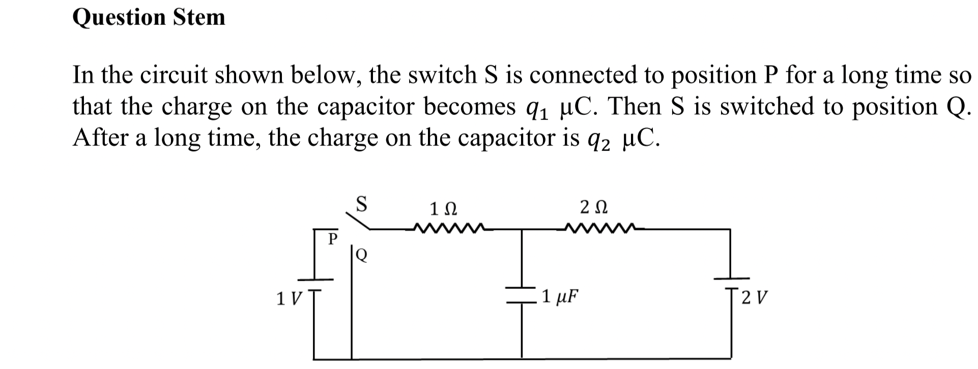
Q8: \(\frac{4}{3}\,\mu\text{C}\text{,}\) Q9: \(\frac{2}{3}\,\mu\text{C}\text{.}\)
Since capacitor would be fully charged, there will be no current in the branch that has capacitor. Therefore, same current \(I\) will flow in the a-d-b-c-a circuit.
Starting at point b, where we will choose the ground, hence \(V_b=0\text{,}\) and going counterclockwise, Kirchhoff's loop rule gives
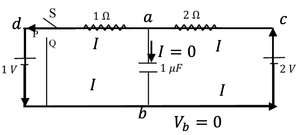
Therefore \(I = \frac{1}{3}\text{.}\) By using \(I\text{,}\) we can get voltage at point a.
Since \(V_c = 2\text{ V}\text{,}\) we get \(V_a = 4/3\text{ V}\text{.}\) Since \(V_b=0\text{,}\) the voltage across capacitor is
Now, using the capacitor formula, \(q = C\Delta V\text{,}\) we get
Again capacitor is fully charged, therefore, there will be no current in the branch that has capacitor. But now, the battery on the left is outside the circuit in which current flows as shown in Figure 1.1.11
Now, from the circuit b-c-a-Q-b, we get
Hence \(I = 2/3\text{ A}\text{.}\)
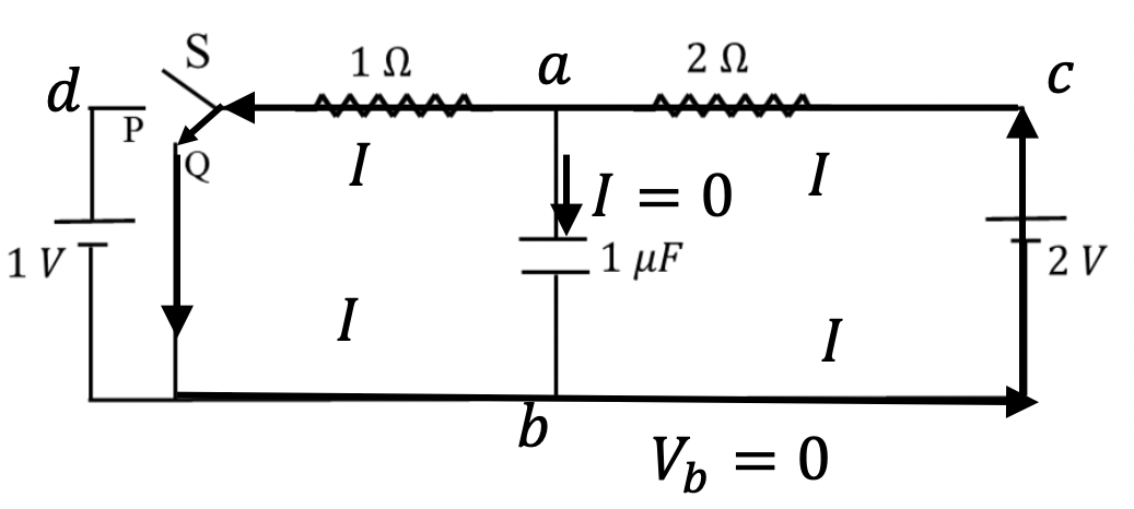
Therefore,
Since \(V_b=0\text{,}\) the voltage across capacitor is
Now, using the capacitor formula, \(q = C\Delta V\text{,}\) we get
Problem 1.1.12. Q9 and Q10: Circular Equipoential.
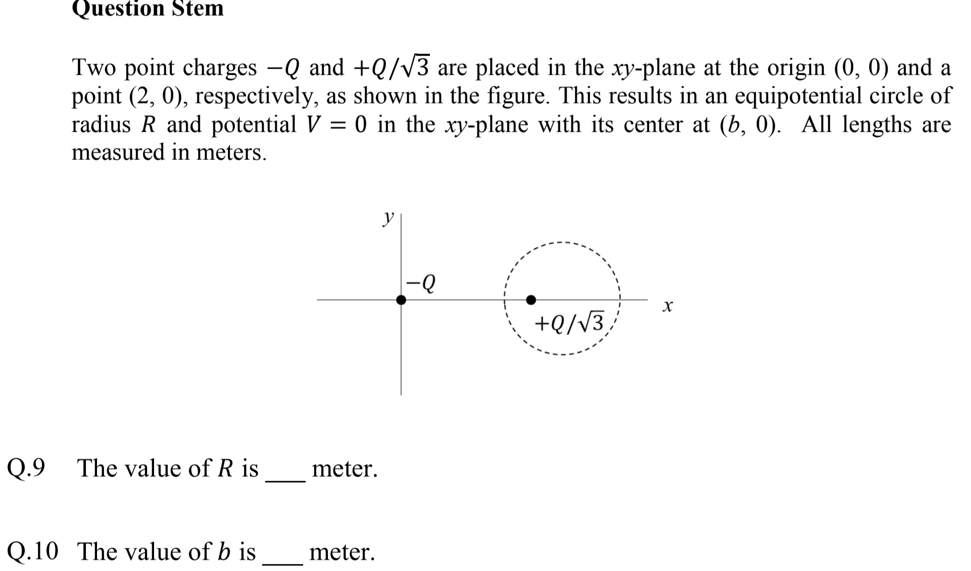
Demand potential at points corresponding to the circle be zero.
Q9: \(R=\sqrt{3}\text{,}\) Q10: \(b=3\text{.}\)
Strategy: I will write potential for general point in \(xy\)-plane and then demand that it be zero at all points of a sphere of radius \(R\) centered about \((b,0)\text{.}\) This should give necessary conditions. For this, we use Figure 1.1.13.

Potential at an arbitray point \(P(x,y)\) by two charges \(-Q\) and Q/\sqrt{3} will be
When \((x,y)\) is on sphere \((x-b)^2 + y^2 = R^2\text{,}\) potential would be zero. That is,
Hence, we have
Squaring and then cross-multiplying gives us the following condition.
Since this must be true for every \(x\) on the sphere. That means, we must have
These can be solved to yield \(b=3\text{,}\) and \(R=\sqrt{3}\text{.}\)
Problem 1.1.14. Q11: Rolling Motion.
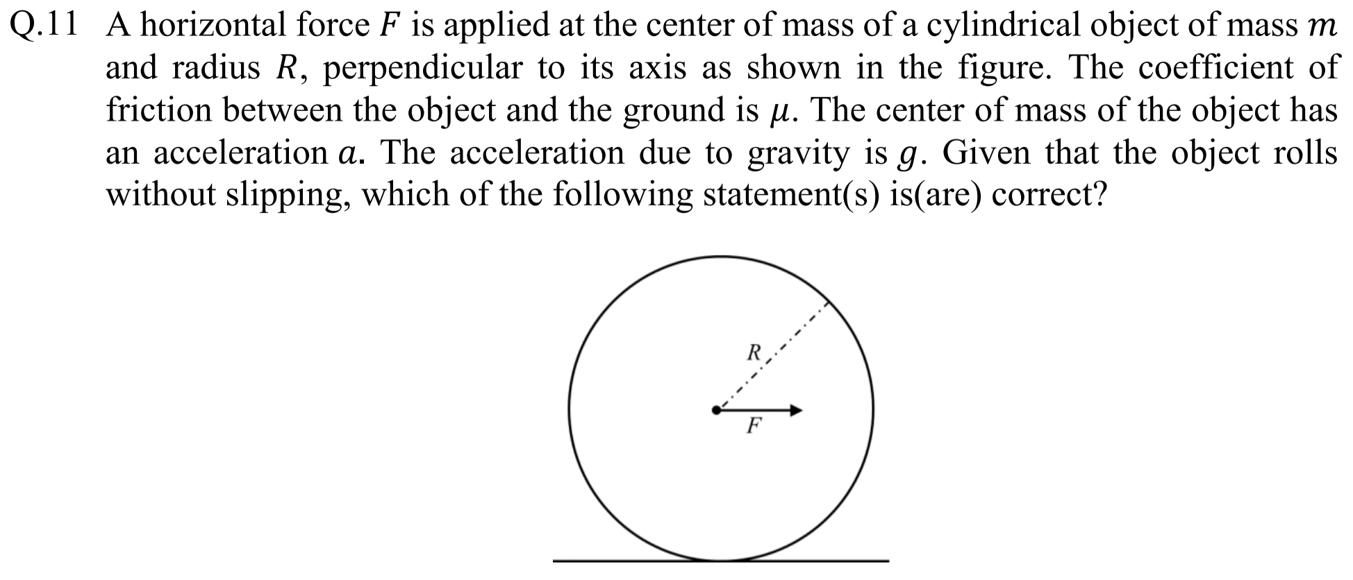
(B), (D).
To check answer (A), we note forces on the rolling cylinder. The rotational equation of motion about point O, which is momentarily at rest is
where \(\alpha\) is angular acceleration.
Since rolling cylinder is not slippling, the center of mass motion is related to rotation such that acceleration of the CM will be
Hence,
Since \(I_\text{abt O}\) depends on whether the cylinder is hollow or solid, \(a\) will depend on this aspect of cylinder. Hence, (A) is false.
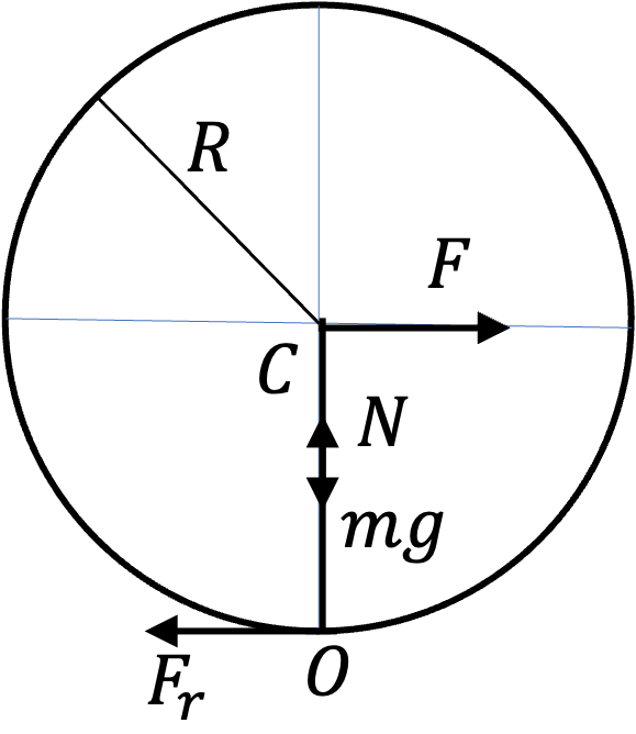
Using Figure 1.1.15, we can write equation of motion about the center as
where \(I_0 = \frac{1}{2}mR^2\) is moment of inertia about the CM. Assuming maximum rolling friction, we will have \(F_r = \mu N\text{.}\) Since no acceleration of the CM in the vertical direction, we also have \(N-mg=0\text{.}\) Hence, acceleration of CM will be
This says (B) is correct.
(C) is not correct since only maximum rolling friction will be \(\mu N=\mu m g\text{.}\)
The moment of inertia of a thin-walled cylinder about its symmetry axis through the CM is
Using parallel axis theorem, we get moment of inertia about O, the point touching the ground to be
Therefore, using Eq. (1.1.5), we get acceleration of the CM to be
Hence, (D) is correct.
Problem 1.1.16. Q12. Refraction Through Parallel Plates.
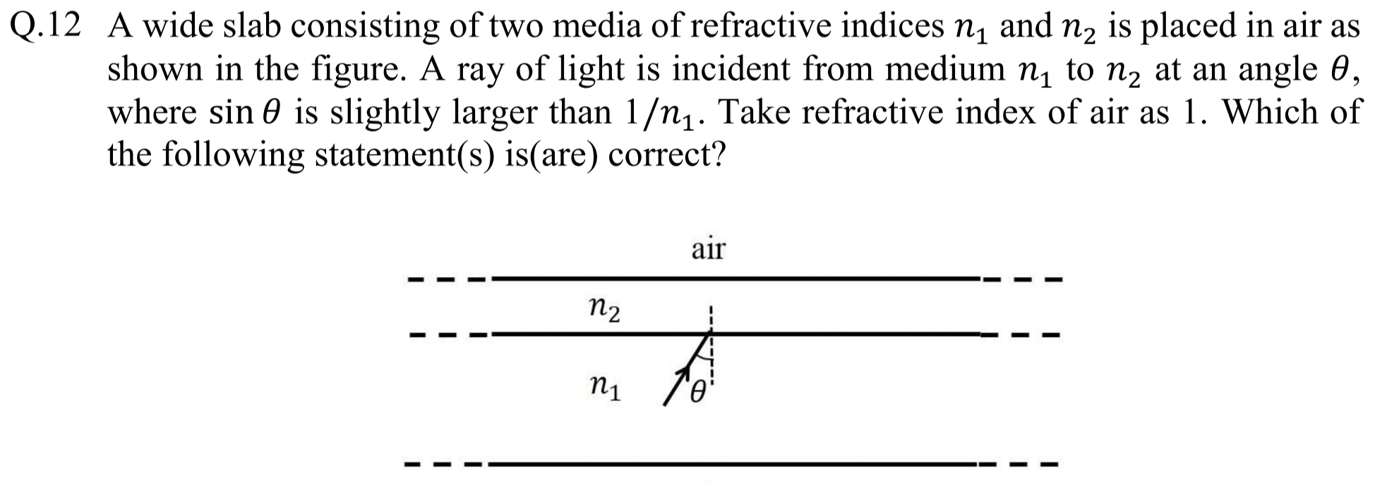
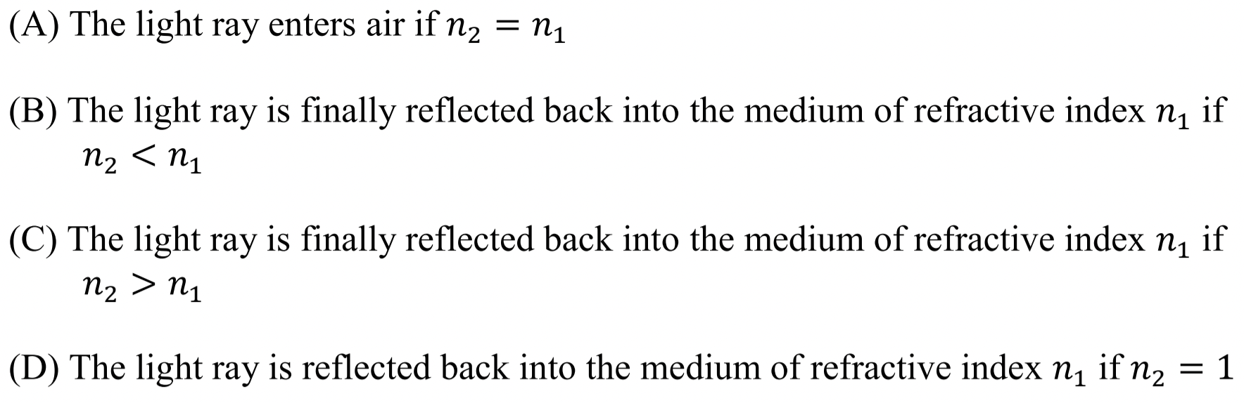
Make use of \(\sin\theta \gt 1/n_1\) and if \(x\) is real then \(\sin\, x\lt 1\text{.}\)
(B), (C), (D).
Main idea: \(x\) is not a real number if \(|\sin(x)| \gt 1\text{.}\) The incident ray in medium \(n_1\) has angle \(\theta\) such that \(\sin\theta \gt 1/n_1\text{,}\) i.e., \(n_1 \sin\theta \gt 1\text{.}\)
Choice (A) has case \(n_1=n_2\text{.}\) That would mean \(\theta_2=\theta\text{.}\) Therefore, we will have
With \(n_0=1\) and \(n_1\sin\theta \gt 1\text{,}\) this will mean \(\sin\phi \gt 1\text{,}\) which is not possible for real \(\phi\text{.}\) Therefore (A) is incorrect.

Choice (B) has case \(n_2 \lt n_1\text{.}\) Figure 1.1.18 shows two ways, ray from \(n_1\) can turn back into \(n_1\) wwithout any transmission into air. Another way to answer this question is to just look at the second of these:

Since \(n_2 \lt n_1\text{,}\) there would be some \(\theta\) at which this condition will have \(\sin\theta_2\gt 1\text{,}\) i.e., we wil lget total internal reflection back into \(n_1\text{.}\) Thus, (B) is correct.
Choice (C) has case \(n_1 \lt n_2\text{.}\) Figure 1.1.19 shows a ray diagram for this situation.
This \(\theta_2\) is always possible. Let's look at the \(n_2/n_0\) interface.

At \(n_2/n_0\) interface we have
Hence, this \(\phi\) is not possible. Hence, the ray will return back to \(n_1\text{.}\) That is, (C) is correct.
For (D), We have \(\theta_2=\phi\text{,}\) and we get
Hence, ray will be reflected back in \(n_1\text{.}\) That is, (D) is correct.
Problem 1.1.20. Q13. Vector Mechanics.
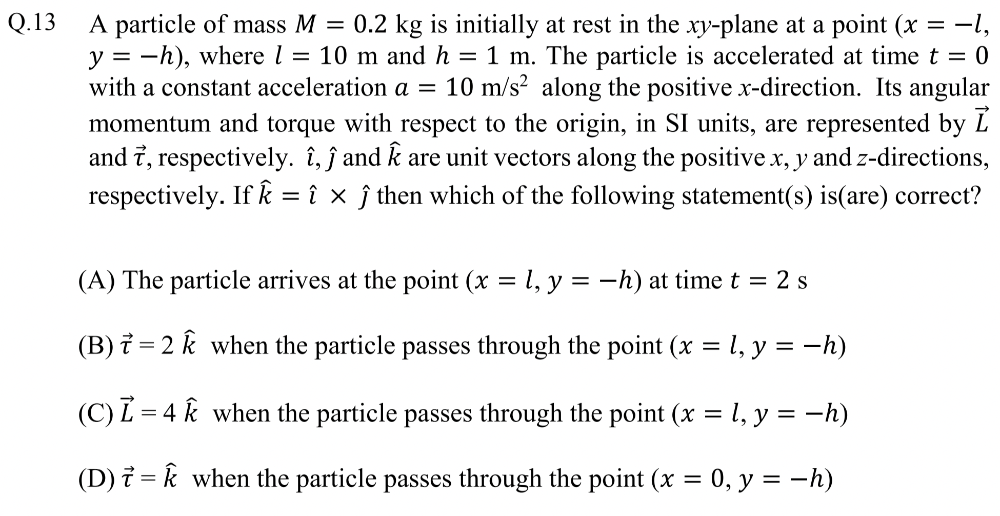
Use vector forms of mechanical quantities.
(A), (B), (C).
In (A), we are looking at a one-dimensional constant acceleration motion from A to B towards positive \(x\)-axis direction. Hence,
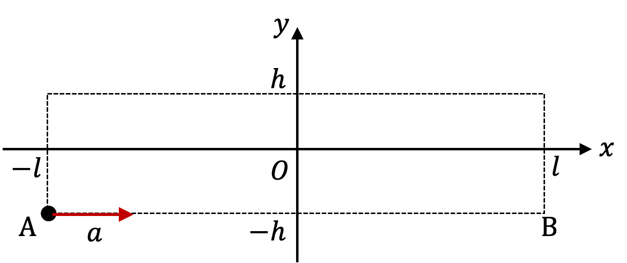
This gives \(t = \sqrt{4l/a} = 2\text{ sec}\text{.}\) (A) is correct.
For (B), we implement definition of torque as \(\vec r \times \vec F\text{.}\)
Therefore, (B) is correct.
(C) First we find velocity at B.
Therefore, angular momentum about O will be
Therefore, (C) is correct.
Torque here is same as we found in (B). That is \(\vec \tau = \vec r \times \vec F = 2\hat k\text{,}\) which means (D) is incorrect.
Problem 1.1.22. Q14. Rydberg Formula.
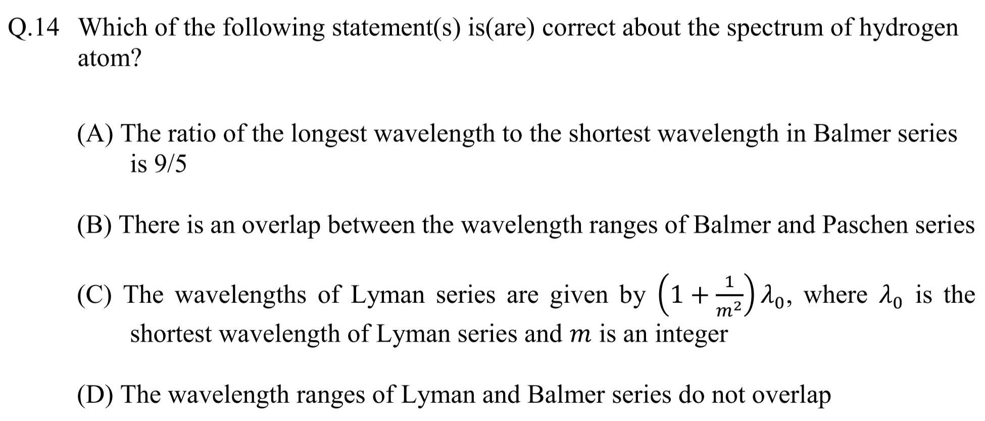
Use Rydberg formula.
(A), (D)
This question is about Rydberg formula.
Here \(n_1=1\) for Lyman series, \(n_1=2\) for Balmer series, and \(n_1=3\) for Paschen series. Shortest wavelength occurs when \(n_2=\infty\text{.}\)
To check (A), we note that longest wavelength for Balmer will occur when \(n_2=3\text{.}\) Therefore, the raito we seek is
That is, (A) is true.
Paschen series is in general higher wavelengths than Balmer. Therefore, for (B), we need to just check whether min wavelength of Paschen series is smaller than max wavelength of Balmer.
Since \(\lambda_\text{min,P} \gt \lambda_\text{max,B}\text{,}\) there is no overlap between the two series. Therefore, (B) is false.
For (C), let's see if we can rewrite formula for Lyman series in the form in the question.
Therefore, (C) is false.
For (D), we need to just check whether min wavelength of Balmer series is smaller than max wavelength of Lyman.
Since \(\lambda_\text{min,B} \gt \lambda_\text{max,L}\text{,}\) there is no overlap between the two series. Therefore, (D) is true.
Problem 1.1.23. Q15. Faraday's Law.
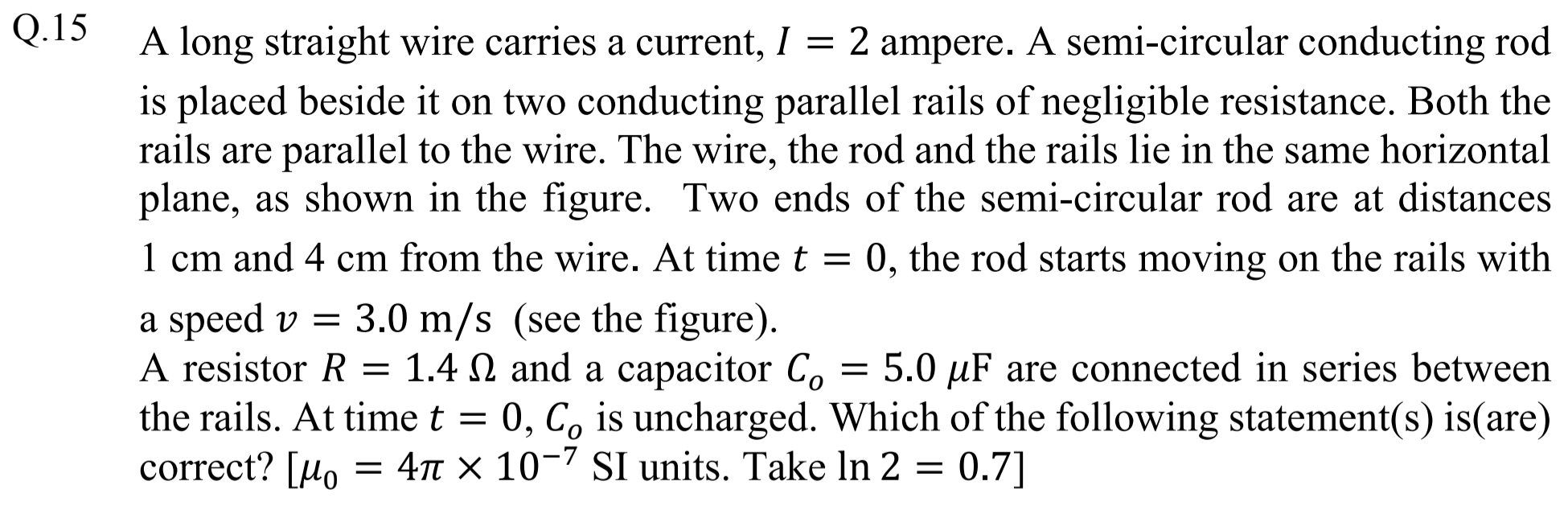
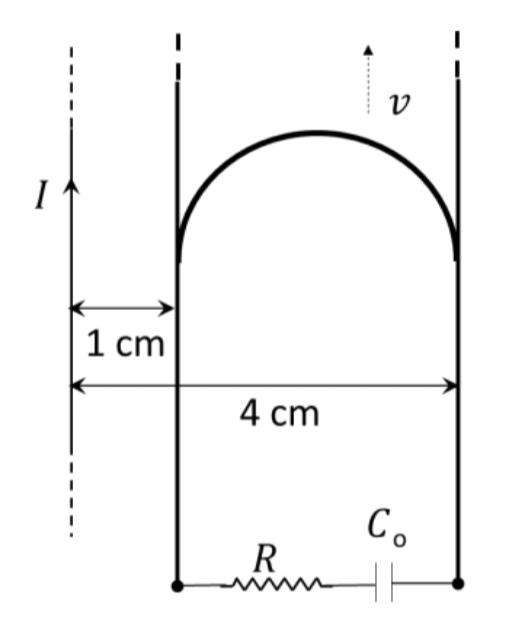
Magnetic flux changed in only rectangular part of the loop.
(A) and (C)
From Figure 1.1.24 we see that the magnetic field of the steady current \(I\) in the straight wire will pass through the area enclosed by the expanding circuit on the right. Hence, magnetic flux \(\Phi_B\) will change in the loop, which will cause induced current \(I_\text{ind}\text{.}\)

Magnetic field at a distance \(r\) from the straight wire carrying steady current \(I\) is
in the direction shown in Figure 1.1.24. Since magnetic flus through the arc part is not changing, we will not compute that.
To calculate magnetic flux through the changing area, we write magnetic flux through a strip at a distance \(r\) as shown in Figure 1.1.25. This will be
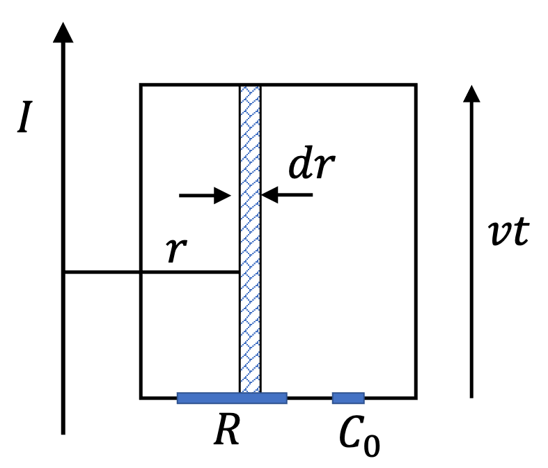
Integrating from \(r=a\) to \(r=b\) we get
Therefore, rate of change of flux will be
That means induced EMF will be
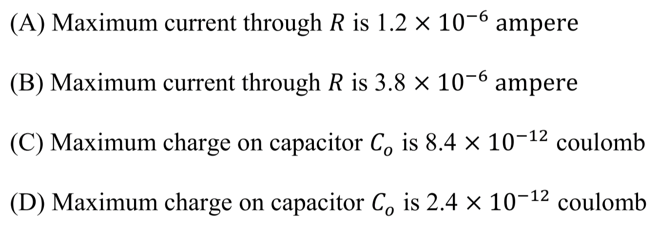
Now, notice that the loop acts as a charging RC-circuit with resistance \(R\text{,}\) capacitance \(C_0\) and EMF \(\mathcal{E}\text{.}\) Therefore, maximum current in this circuit will occur when all EMF falls around the resistor.
When capacitor is fully charged, all voltage will be falling around the capacitor.
Therefore, (A) and (C) are true and (B) and (D) are false.
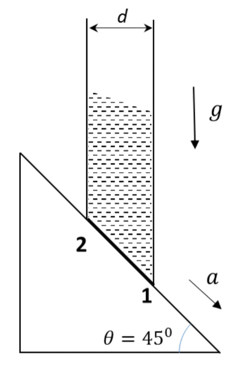
Problem 1.1.26. Q16. Static Pressure in Accelerating Fluid.
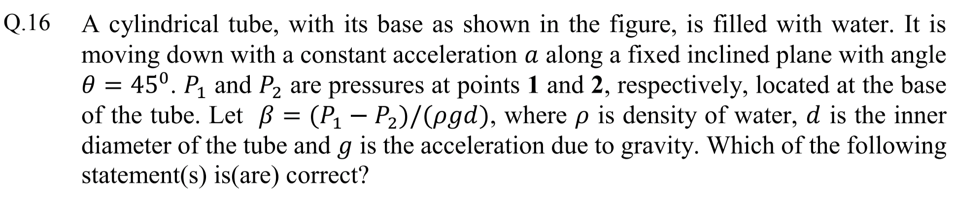
Write \(F=ma\) for an element of fluid at the bottom.
(A) and (C).
We examine an elment of water at the base with area of corss-section \(A\) and length \(d\sqrt{2}\text{.}\) Figure 1.1.27 shows forces \(mg\text{,}\) \(N\text{,}\) \((p_2-p_1)A\text{,}\) and \(F\text{.}\) As a result, the element has acceleration \(a\text{.}\)
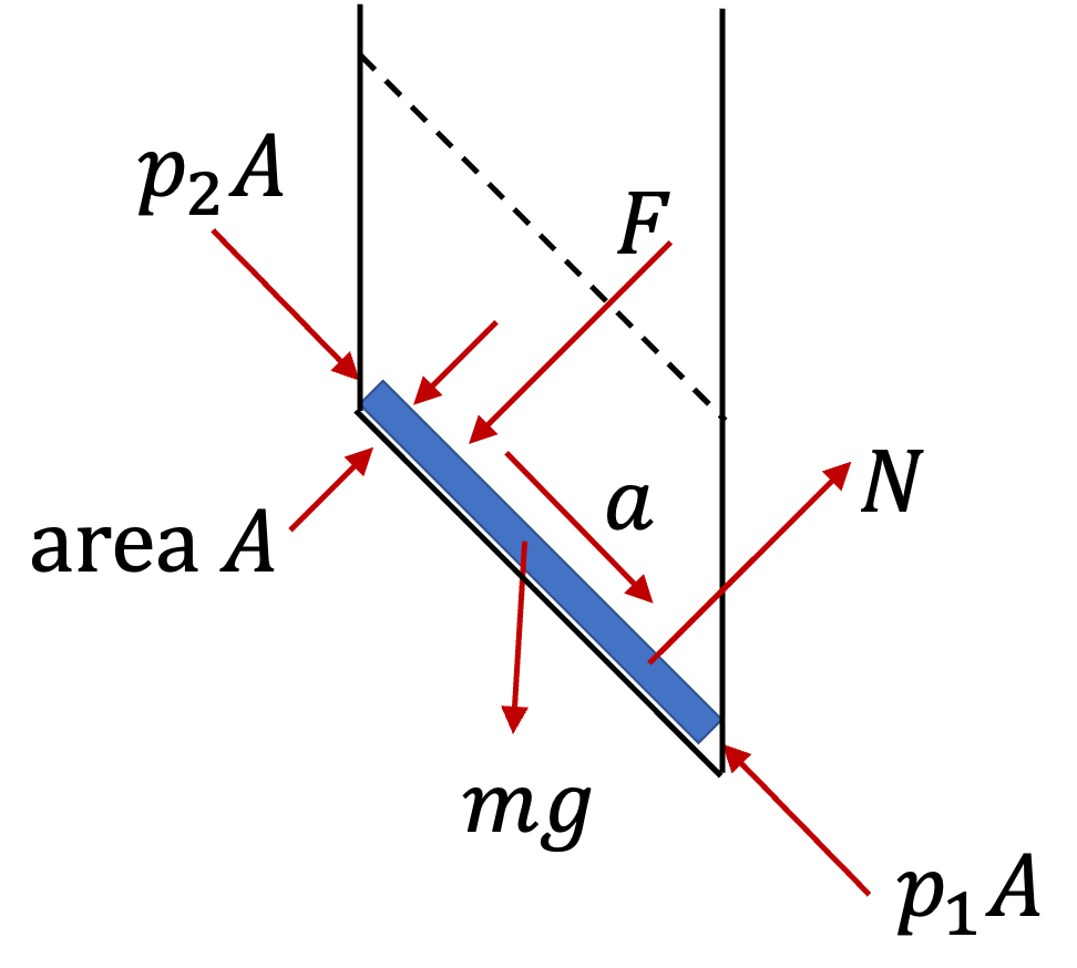
Let \(x\)-axis be pointed down the incline. Then, \(F_{\text{net},x} = ma_a\text{,}\) will be
Here \(m = \rho A d\sqrt{2}\text{.}\) For \(p_1-p_2\) we get
Therefore, \(\beta\) defined in the problem has
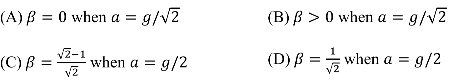
Now, we check answers given for various values of \(a\text{.}\)
(A) and (B): When we use \(a= g/\sqrt{2}\) in Eq. (1.1.6), then we do get \(\beta-0\text{.}\) Therefore, (A) is true and (B) is false.
(C) and (D): When we use \(a= g/2\) in Eq. (1.1.6), we get
That is (C) is true and (D) is false.
Problem 1.1.28. Q17. Magnetic Force.
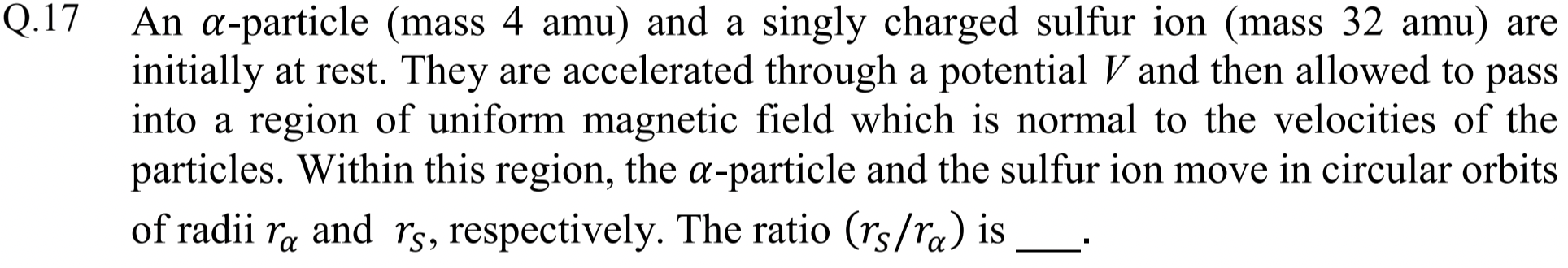
Use energy arguments to find expression for speed and use that in the equation for circular motion.
\(4\text{.}\)
For a particle of charge \(q\) and mass \(m\) moving with speed \(v\) in a circular orbit of radius \(R\) in a magentic field \(B\text{,}\) we will have
Therefore,
Now, in out case, speed is attained by accelerating the particle by a potential \(V\text{.}\)
Hence, for the radius of the orbit, we get
Therefore, the ratio of radii of orbits for two charges we will have
Hence,
Problem 1.1.29. Q18. Addition of Angular Momenta.
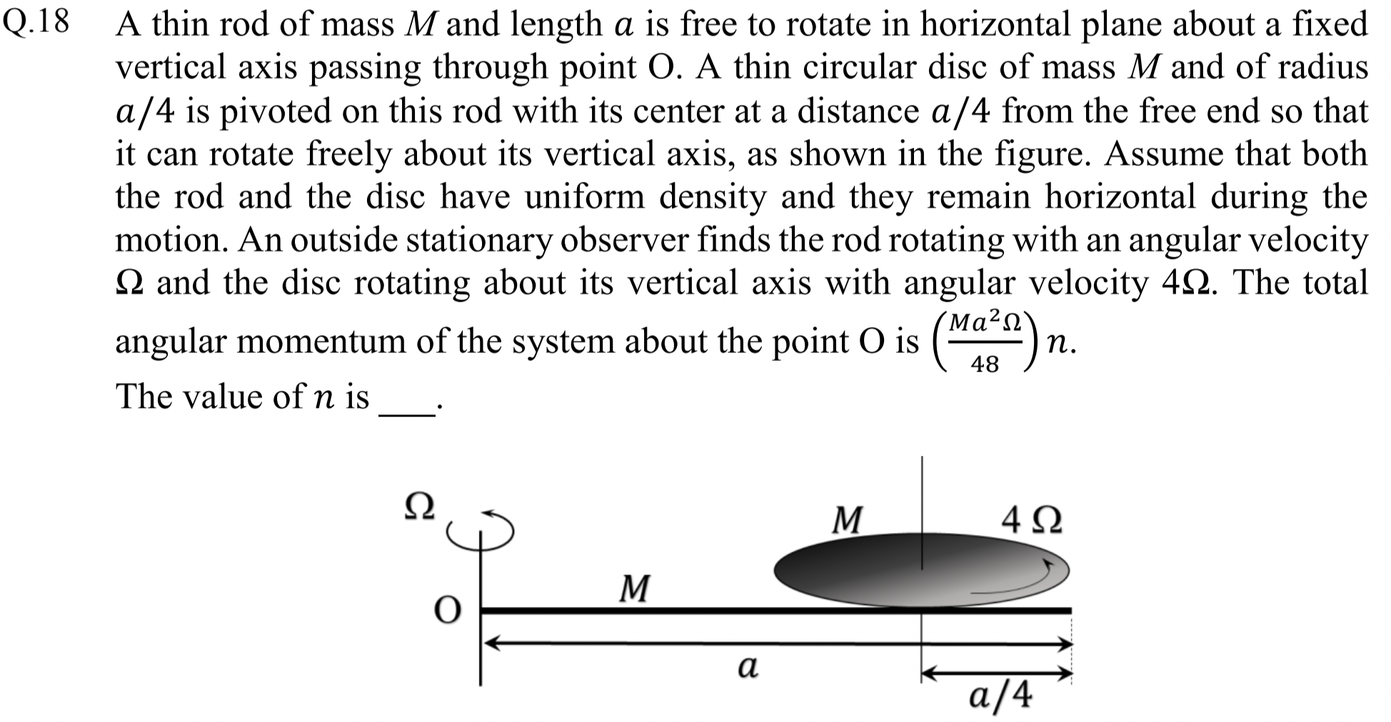
Add angular momenta of rod and disk. For disk, angular momentum will be from spin and from motion of CM.
\(49\text{.}\)
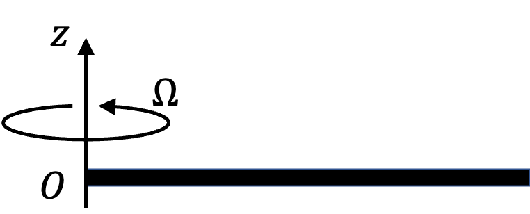
We just add angular momenta of rod and the disk. Let \(z\)-axis be pointed up in the figure.
For rod, angular momentum will be \(I_\text{abt O}\Omega\) pointed towards positive \(z\)-axis. Since axis is at the end of the rod, we have \(I=ML^2/3\) formula.
Now, disk is rotating about an axis through its CM and its CM is also moving. Therefore, we will have

From the counterclockwise spinning of the disk we get
where I have used \(I=\frac{1}{2}MR^2\) formula for the disk with \(R=a/4\text{.}\)
Now, the CM is located at a distance \(3a/4\) from O about which CM is moving in a circle with angular speed \(\Omega\) as shown in Figure 1.1.31. Therefore,
Using right hand rule for cross product we get the direction to be also towards positive \(z\)-axis. Therefore,
Adding all angular momenta, we have
Hence, answer is \(n=49\text{.}\)
Problem 1.1.32. Q19. Balckbody.
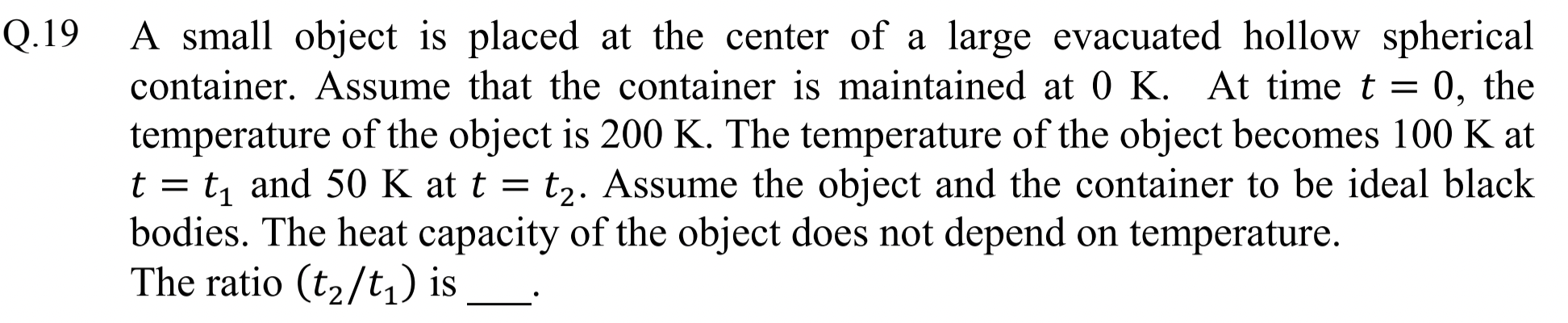
Equate the rate at which temperature drops to the rate at which energy radiate out.
\(9\text{.}\)
We will need two formulas for this problem. (1) One is the formula for power radiated from the object which is taken to be a blackbody at temperature \(T\) to the outer container kept at zero degree Kelvin.
where \(A\) is the surface area of the body, \(\epsilon\) its emissivity, and \(\sigma\) is a universal constant - we do not need values of these quantities for this problem since they will cancel out in the end. If hollow container was not at zero degree kelvin, it will also emit radiation, some of which will be absorbed by the body; in that case we would have \(P = \sigma \epsilon A T^4\) \(- \sigma a A T_\text{container}^4\text{,}\) but we do not have this here.
(2) The other formula we need is for the rate of decrease of temperature of the body as a result of loss of energy \(U\) in the form f heat.
Since, body lose energy only by radiation, we can equate the rate of decrease of energy of the body to the rate of radiation of energy from the body to get the necessary equation for solving this problem.
Therefore,
Solving this differential equation, from \(T=T_0\) at \(t=0\) to \(T=T\) at \(t=t\text{,}\) we get
We apply this for \(t=t_1\) and \(t=t_2\) given in the problem statement to get
Since ratios will kill common factors, I will divide out given values of temperatures by 100 before using them. This gives