Section 1.2 Paper II
Problem 1.2.1. Q1. Static Equilibrium.
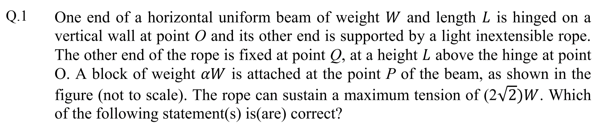
Identify forces on the beam and balance forces and torque about any point.
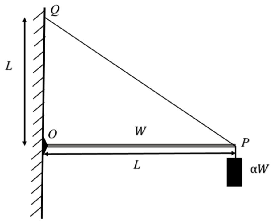
(A), (B), (D)
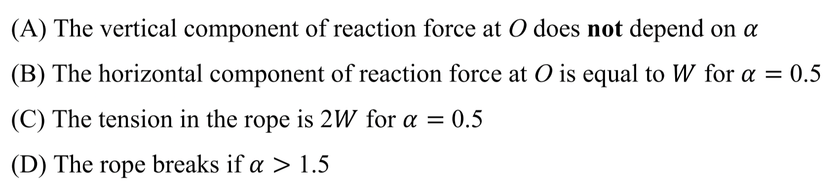
First we identify all forces on the beam as shown in Figure 1.2.2. Force from the wall at O is shown as its components \(F_x\) and \(F_y\text{.}\)
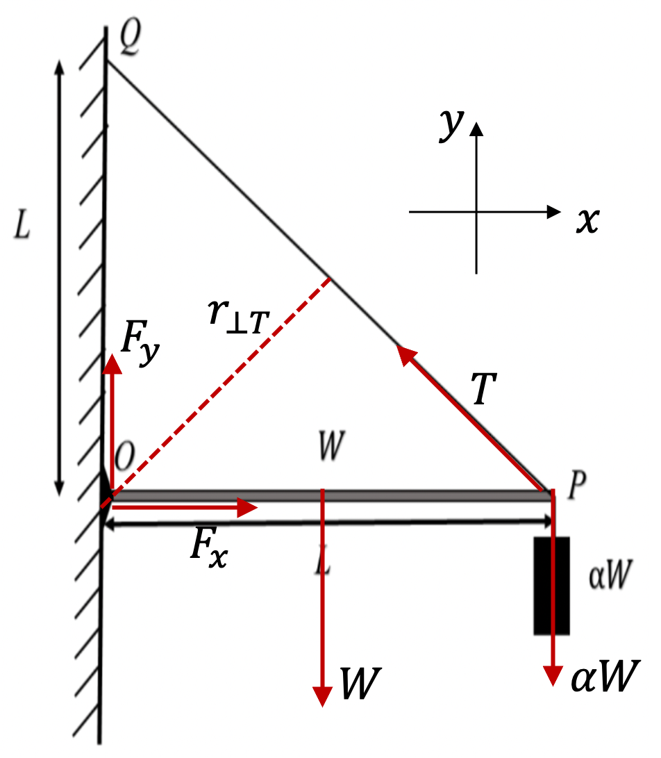
Balancing of force, \(\sum \vec F\) on the beam gives
Balancing torque about O gives
Balancing torque about P gives
Balancing torque about Q gives
To check (A), we look at Eq. (1.2.4). This gives
Clearly independent of \(\alpha\text{.}\) Therefore (A) is ture.
To check (B), we look at Eq. (1.2.5). Therefore
For \(\alpha = 0.5\text{,}\) this gives \(F_x = W\text{.}\) Hence, (B) is true.
Using (1.2.1) and \(F_x\) from (1.2.6) we get
For \(\alpha = 0.5\text{,}\) this givbes \(T=\sqrt{2} W \ne 2W\) . Hence (C) is false.
Rope will break if \(T \gt T_\text{max} = 2\sqrt{2}W\text{.}\) Therefore from Eq. (1.2.7). This will give us \(\alpha\text{.}\)
Thus (D) is true.
Problem 1.2.3. Q2. Doppler Effect.
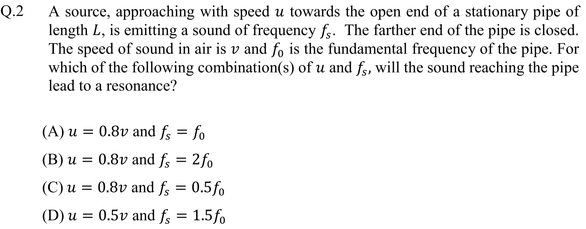
Doppler shifted frequency should match resonance frequency of the tube.
(A), (D)
Let \(v\) be speed of sound in the medium and \(u\) speed of source moving towards the tube. Then, the frequency at the tube will be shifted upwards given by
Let \(nf_0\) with \(f_0=4c/L\) and \(n=1,\, 3,\, 5,\cdots\text{.}\) For resonance, we must meet the following condition for some allowed \(n\text{.}\)
We can write this as
We use this equation to answer questions.
For (A), we have \(u=0.8v\) and \(f_s=f_0\text{.}\) This will mean
This is an odd integer. There will be resonance for this condition. Thus, we have yes for (A).
For (B), we have \(u=0.8v\) and \(f_s=2f_0\text{.}\) This will mean
This is an even integer. There will be no resonance for this condition. Thus, we have no for (B).
For (C), we have \(u=0.8v\) and \(f_s=0.5f_0\text{.}\) This will mean
This is not an odd integer. There will be no resonance for this condition. Thus, we have no for (C).
For (D), we have \(u=0.5v\) and \(f_s=1.5f_0\text{.}\) This will mean
This is an odd integer. There will be resonance for this condition. Thus, we have yes for (D).
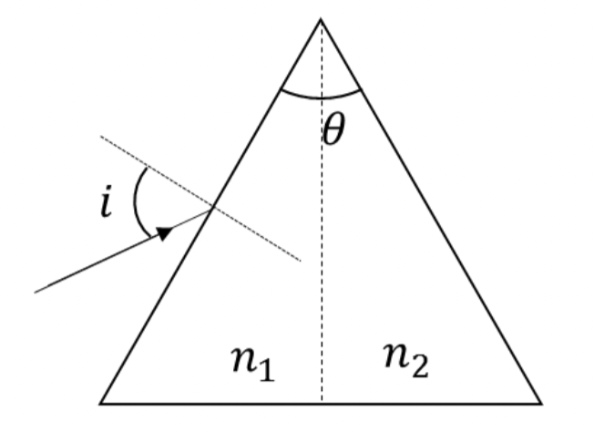
Problem 1.2.4. Q3. Minimum Deviation in Prism.
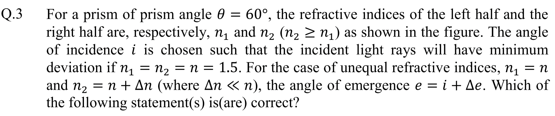
Minimum deviation ray passes horizontally through the isosceles prism.
(B) and (C).
In Figure 1.2.5 ray ABCD is minimum deviation ray which is symmetric when \(n_1=n_2\text{.}\) When \(n_2 \ne n_1\text{,}\) (in the figure \(n_2 \gt n_1\)), emerging ray goes in the direction CE.
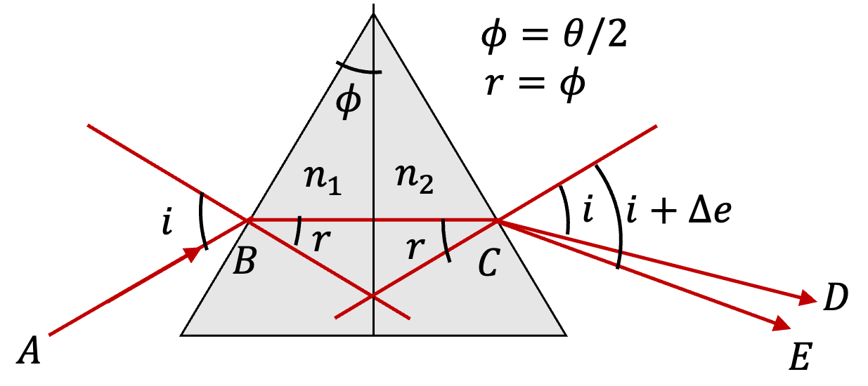
By using complimentary angles in various triangles in the diagram, you can easily show that
From the first interface with \(n_1=n=1.5\) we get
Hence,
From the second interface, with \(n_2 = n + \Delta n\) we get
We expand right side and use \(\Delta e \ll 1\) so that
to get
Since \(\sin\,i = n\,\sin\, r\text{,}\) this simplifies to
We can write this as
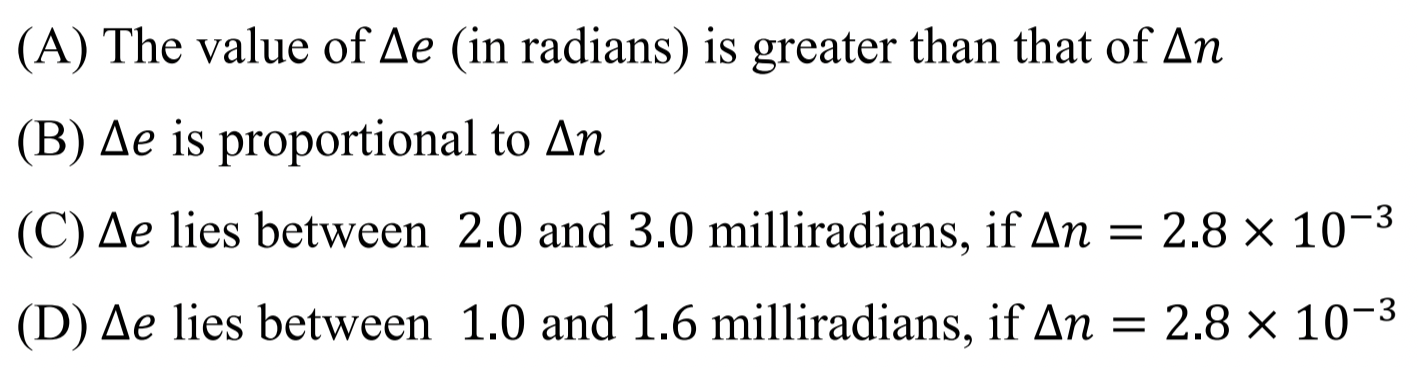
Putting in numerical values, \(n=1.5\) and \(i=48.6^\circ\text{,}\) this becomes
This shows that \(\Delta e \lt \Delta n\text{.}\) Hence (A) is false. This also shows that \(\Delta e \propto \Delta n\text{.}\) Hence (B) is true.
For \(\Delta n = 2.8\times 10^{-3}\text{,}\) we get
Hence (C) is true and (D) is false.
Problem 1.2.6. Q4. Dimensinal Analysis.
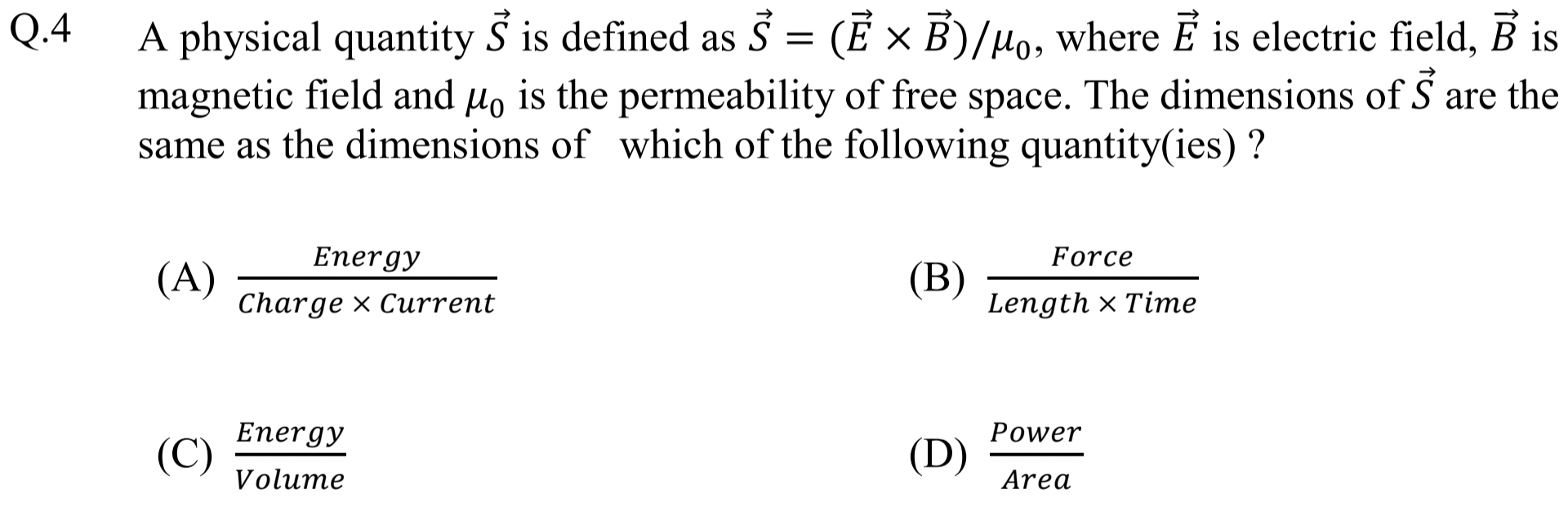
Just check units.
(B), (D).
I just use \(B=\mu_0 I/2\pi r\) of a straight wire to get rid of \(B\) and \(\mu_0\) to help checking with units. Also current is just charge over time. Thus dimesnionally speakig we have
This is (B). We can write \([F][r]/[r]^2[t]\text{,}\) which will be \([\text{energy}]/[\text{area}][t]\text{,}\) which actually will be (D) since power has units of energy over time. Hence, answers are only (B) and (D).
Problem 1.2.7. Q5. Nuclear Reactions.
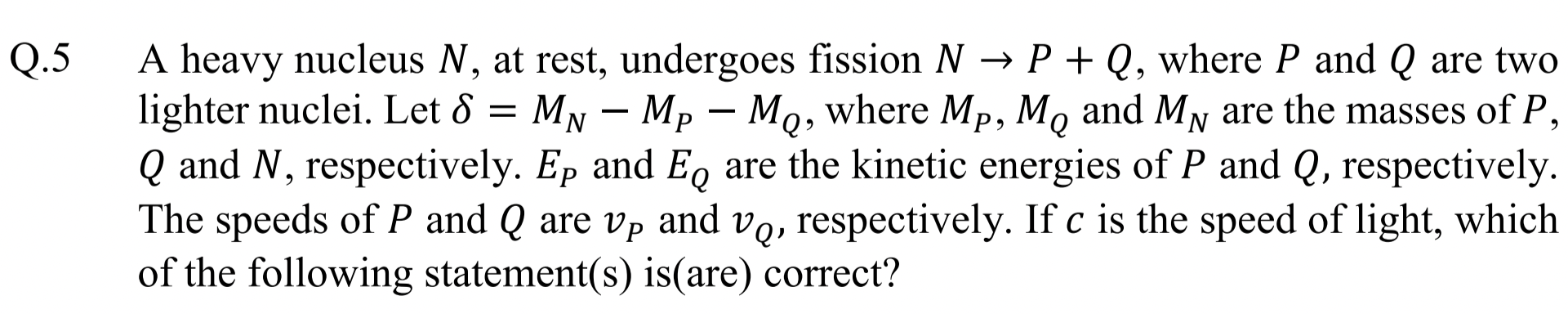
Assume nuclear binding energy per nucleon is same in the three nuclei and apply conservation of energy using missing mass.
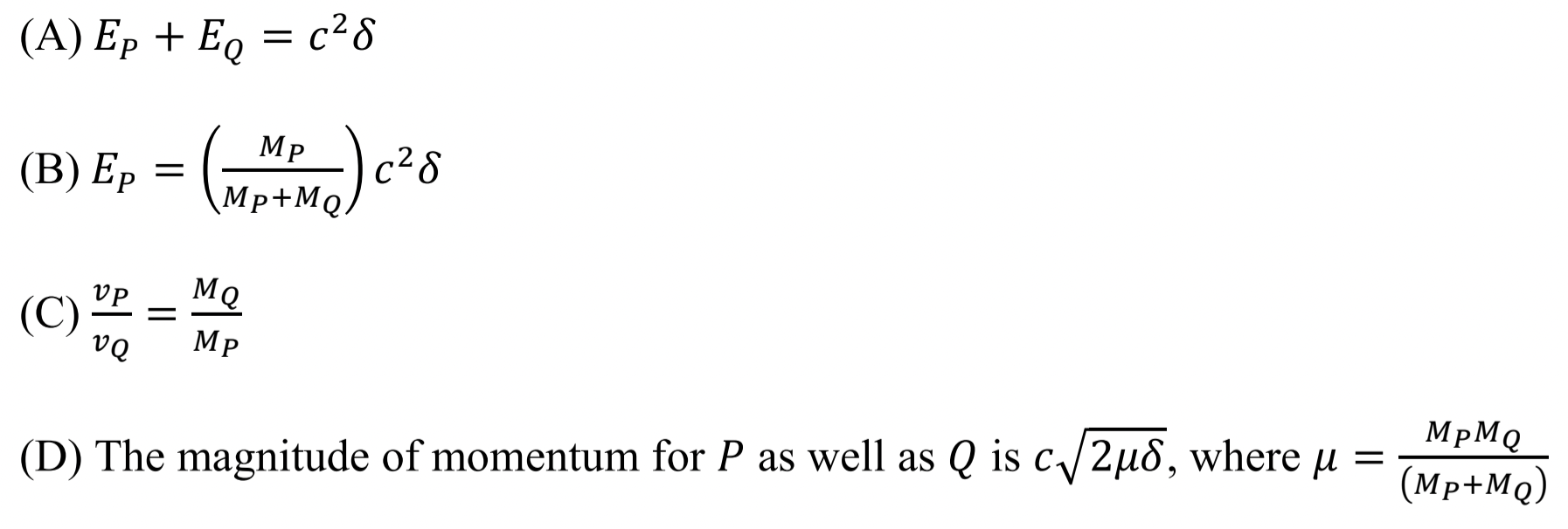
(A), (C), (D).
(A) and (B): Assuming binding energy per nucleon is same in \(N\text{,}\) \(P\text{,}\) and \(Q\text{,}\) missing mass will be converted to kinetic energy.
That says (A) is true and (B) is false.
For (C), we apply momentum conservation of the reaction. Since \(N\) is at rest, we will get
Therefore (C) is true.
For (D), we will work out momentum of \(P\text{.}\) Writing kinetic energy \(E=p^2/2m\text{,}\) we convert Eq. (1.2.10) as
Now, we use Eq. (1.2.11) to replace \(p_Q\) in this equation.
Hence
Taking square root gives us the expression for \(p_P\) in (D). So, (D) is true.
Problem 1.2.8. Q6. Biot-Savart Law.
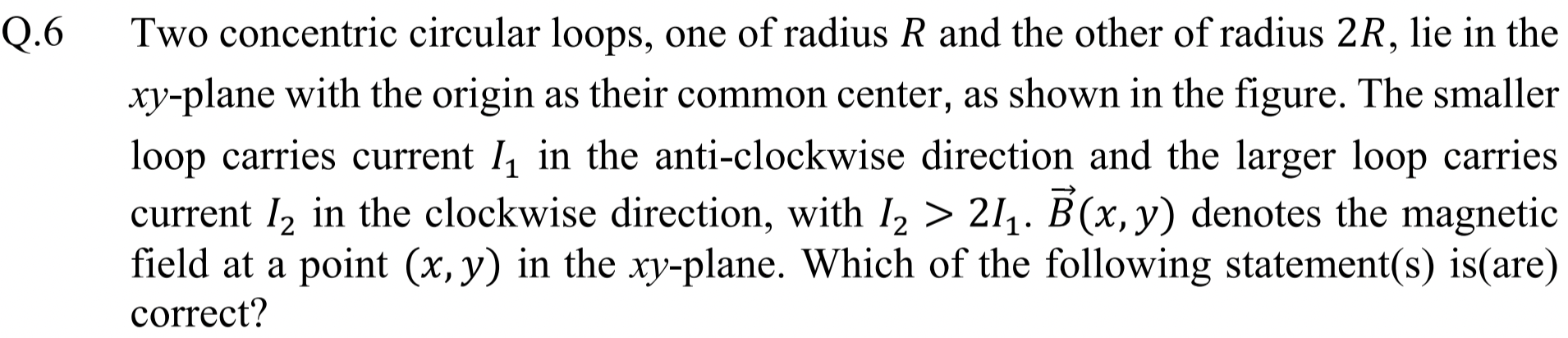
Use Biot-Savart law and symmetry.
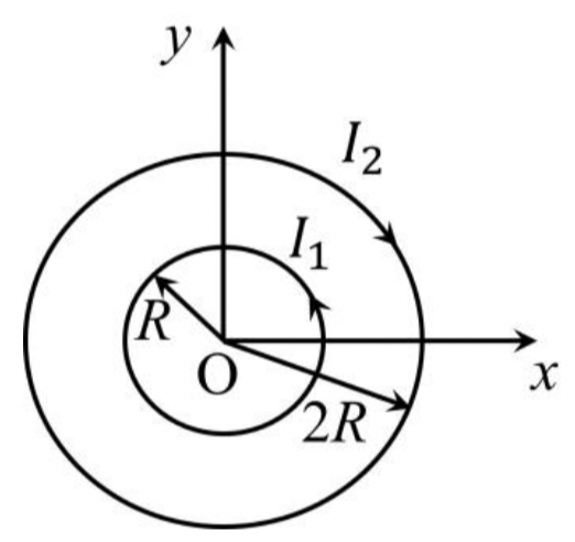
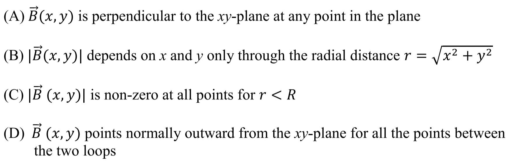
(A), (B).
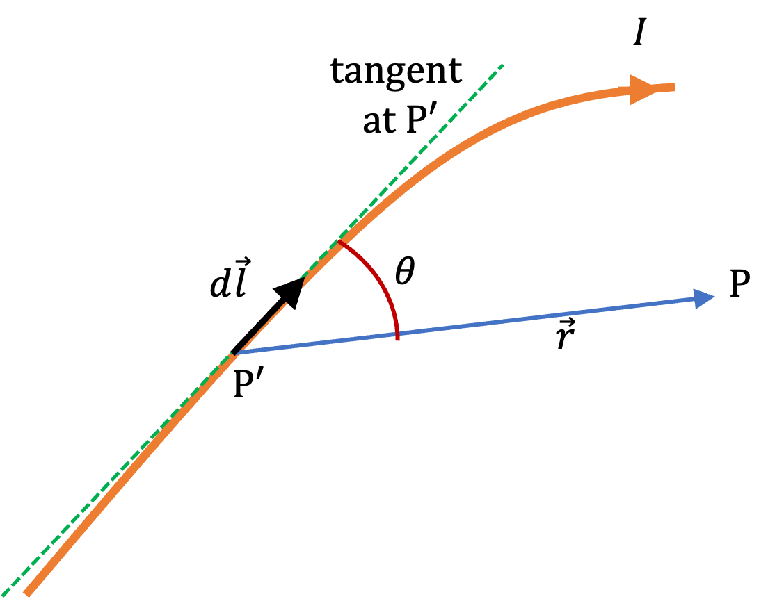
Let's recall Biot-Savart's law for magnetic field at point P due to a current with geometry shown in Figure 1.2.9.
Here \(d\vec l\) is an element of the circuit in the direction of current, \(\vec r\) is the displacement vector from the element of the circuit and the field point P.
To check (A), we note that vector element \(d\vec l\) of both circuits and the displacement vector \(\vec{\mathcal{r}}\) are vectors in \(xy\)-plane. Cross-multiplication of two vectors in \(xy\) plane will result in a vector perpendicular to the \(xy\)-plane. Hence, (A) is true.
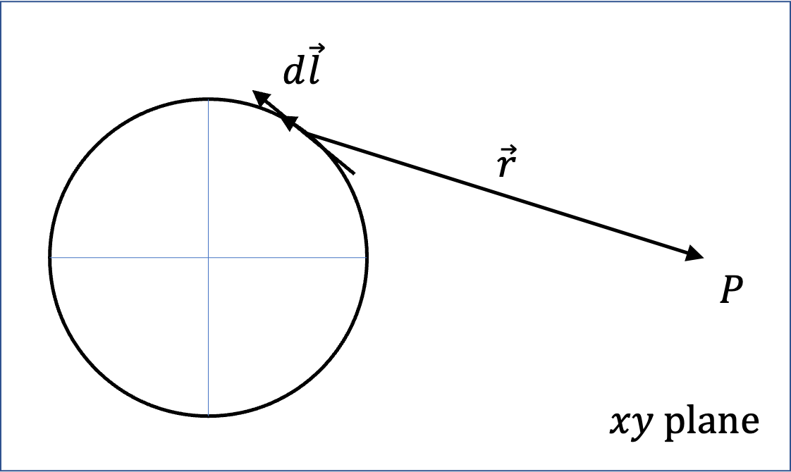
To check (B), we note that currents have a rotational symmetry about \(z\)-axis. That would mean the result of integration in (1.2.12) would only depend on \(r=\sqrt{x^2+y^2}\text{.}\) So, (B) is also true.
To check (C), we just need to show that the claim in (C) is false for even one point. A point that is easy to check using (1.2.12) is the field at the origin. The integral gives the following for inner circuit.
From this we can immediately see that for the outer cirrcuit we will be
The vector sum will give zero. That means net field is zero at least at the center. Hence, (C) is false.
(D) is definitely false since field will be in the direction \(\pm\hat k\) as we established when discussing (A) above.
Problem 1.2.11. Q7 and Q8: Buoyancy.
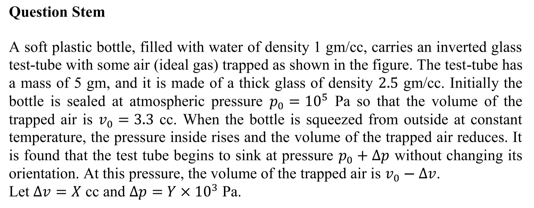
Express buoyancy in terms of volume of glass and the volume inside the test tube.
Q7: \(0.3\text{,}\) Q8: \(10\text{.}\)
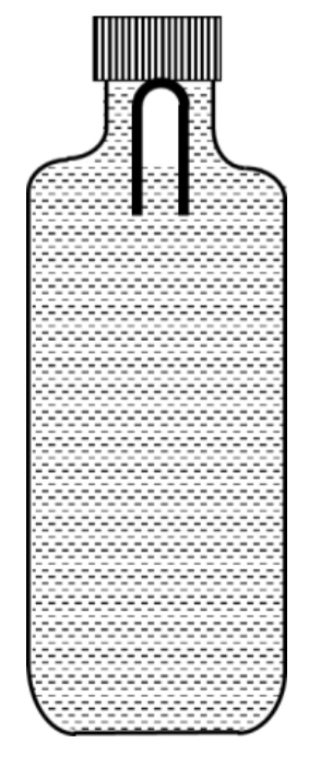
Figure 1.2.12 shows the physical process for this problem. Before squeezing the bottle, the force diagram shows that force by the cork is present to balance the buoyancy force \(F_B\text{.}\) As the problem says, pressure inside the trapped air is increased to the point when tube starts to sink, meaning \(F_\text{cork}\) becomes zero.
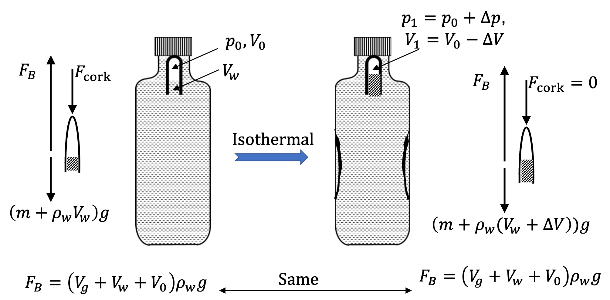
The buoyancy force can be written in terms of volume occupied by glass, \(V_g\text{,}\) and the inside volume of the tube, which is sum of unknown \(V_w\) in the figure and known \(V_0\text{.}\)
where \(V_g\) can be computed from the mass \(m\) and density \(\rho_g\) of glass.
Now, we work out the equilibrium condition in the force diagram on the right side of Figure 1.2.12, where buoyancy balances weight of glass and water in the tube.
Simplifying and then solving for \(\Delta V\text{,}\) we get
Hence answer to Q7 is \(X=0.3\text{.}\)
To find \(\Delta p\text{,}\) we utilize the information that the squeezing the trapped air, to be treated as an ideal gas, occurs at constant temperature. In that case, we will have
This will give us
Expanding and simplifying we get
Hence, answer for Q8 is \(Y=10\text{.}\)
Problem 1.2.13. Q9 and Q10: Angular Momentum.
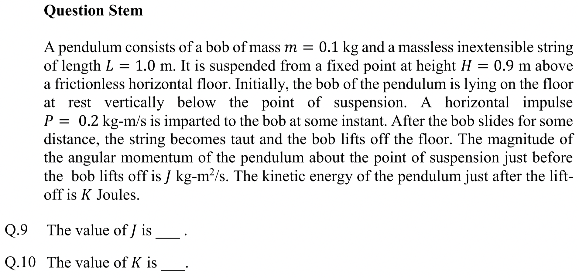
Angular momentum is conserved during liftoff from floor.
Q9: \(0.18\text{,}\) Q10: \(0.16\text{.}\)
The left pannel of Figure 1.2.14 shows overall motion of pendulum bob and the right panel gives situation before liftoff at B and an instant after.
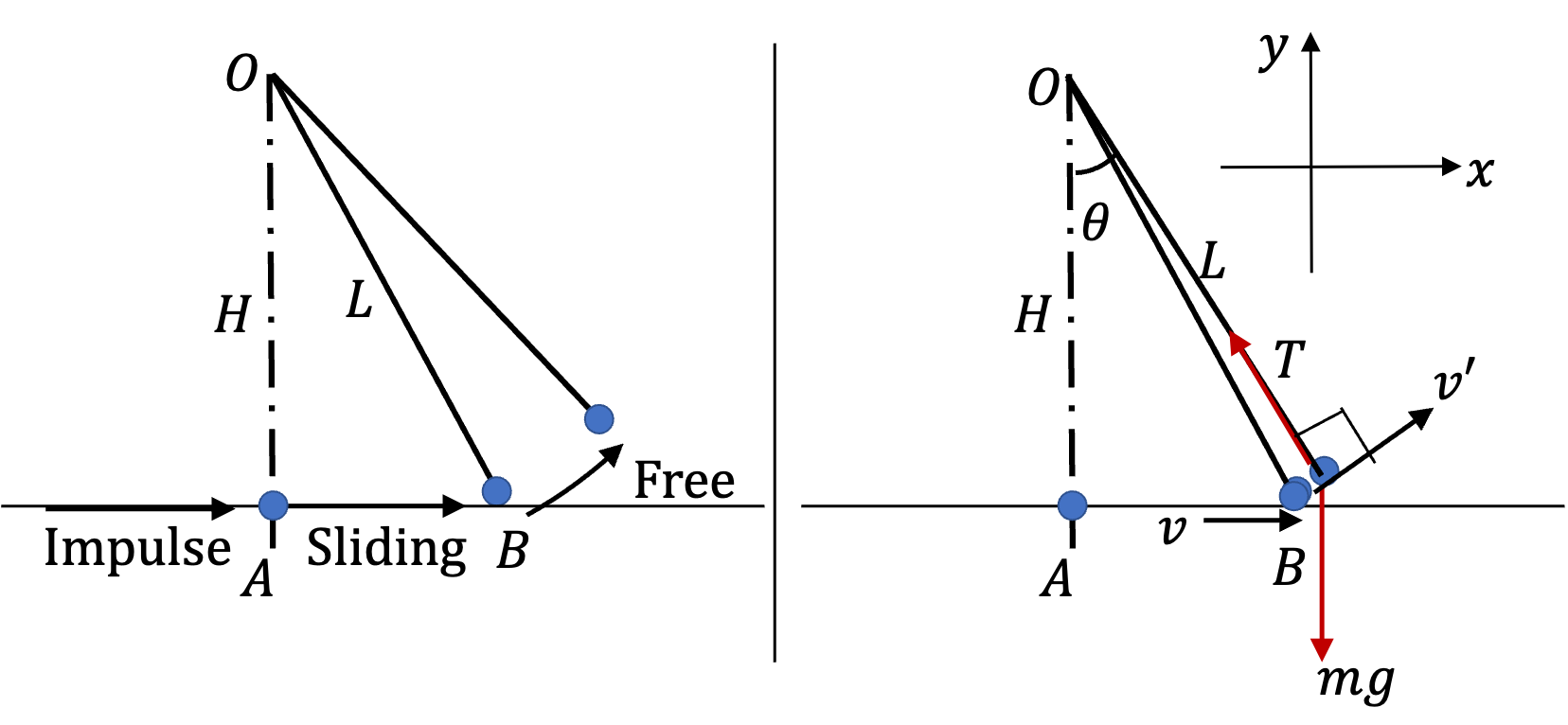
At A, the impulse will change momentum of the bob. Let \(v_A\) be speed of bob as a result of the impulse, then, using \(\Delta p_x = J_x\) for horizontal direction, we get
Because the bob will be sliding frictionlessly and loose string, this velocity will remain unchanged. That is bob arrives at B with velocity \(2\text{ m/s}\) towards positive \(x\)-axis.
At B, the string becomes taut and the bob lifts off. Looking at the right panel in Figure 1.2.14, we notice that only weight has nonzero torque about O. But, in the infintesimal time between just before and just after liftoff its rotational impulse will be negligible. That means, angular momentum of the bob will be conserved during the liftoff at B.
We recall the definition of angular momentum of point particle of mass \(m\) with velocity \(\vec v\) at position \(\vec r\) to be
From the figure we have before liftoff \(\vec r\times \vec v = Hv\) and after liftoff \(\vec r\times \vec v = Lv'\text{.}\) Therefore, we must have
Hence,
Now, we can write the answers for Q9 and Q10. Angular momentum before liftoff is
Hence, \(J=0.18\) for Q9.
For Q10, we need kinetic energy after liftoff.
Problem 1.2.15. Q11 and Q12: AC Circuit.
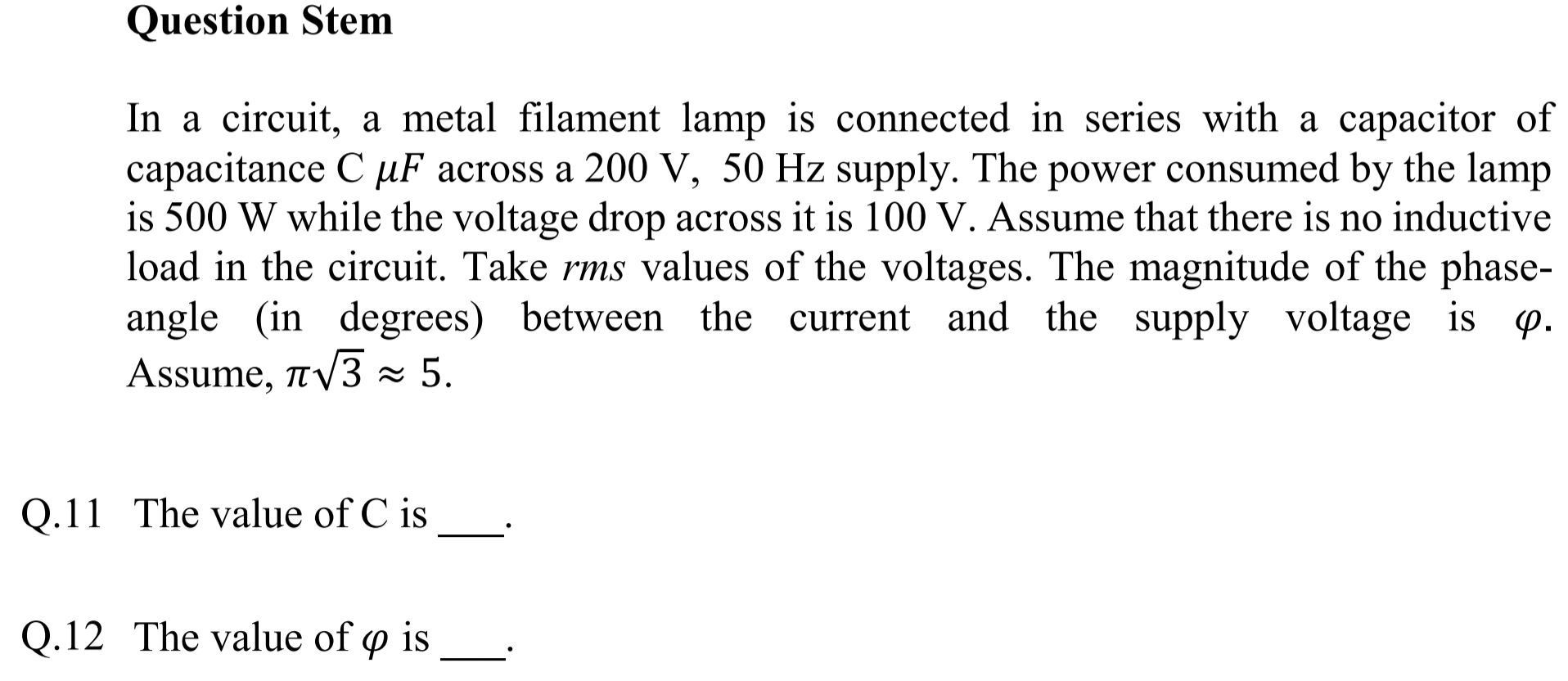
Use standard AC circuit relations.
Q11: \(92\text{,}\) Q12: \(60\text{.}\)
Note that \(200\text{ V},\ 50 \text{ Hz}\) supply means that rms-voltage of the supply is \(200\text{ V}\) and frequency of circuit \(f=50\text{ Hz}\text{.}\) We will need angular frequency \(\omega\) when we work with the capacitor.
From the power \(P\) dissipated in the resistor and rms-voltage \(V_R\) across it, we can get resistance \(R\)by
Therefore, rms-current through the circuit is
This is also rms-current of curren through the power source. Therefore, we can get magnitude of impedance \(Z\) of the circuit from \(I_\text{rms}\) and \(V_\text{rms}\text{.}\)
In the series RC-circuit, the imedance is given by
where \(X_C\) capacitative reactance, given by
Hence, we get
Solving this for \(C\) gives
Now, we use numerical values to get
Phase angle between current through the supply and the voltage of the supply is
Hence, answers are \(92\) for Q11 and \(60^\circ\) for Q12.
Problem 1.2.16. Q13 and Q14: Excluded Magnetic Flux.
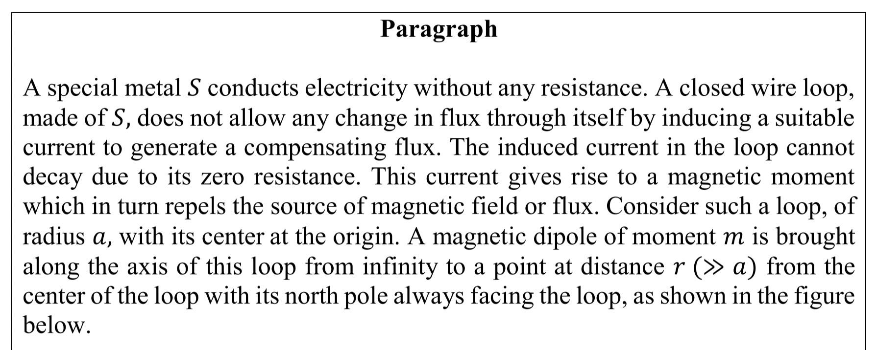
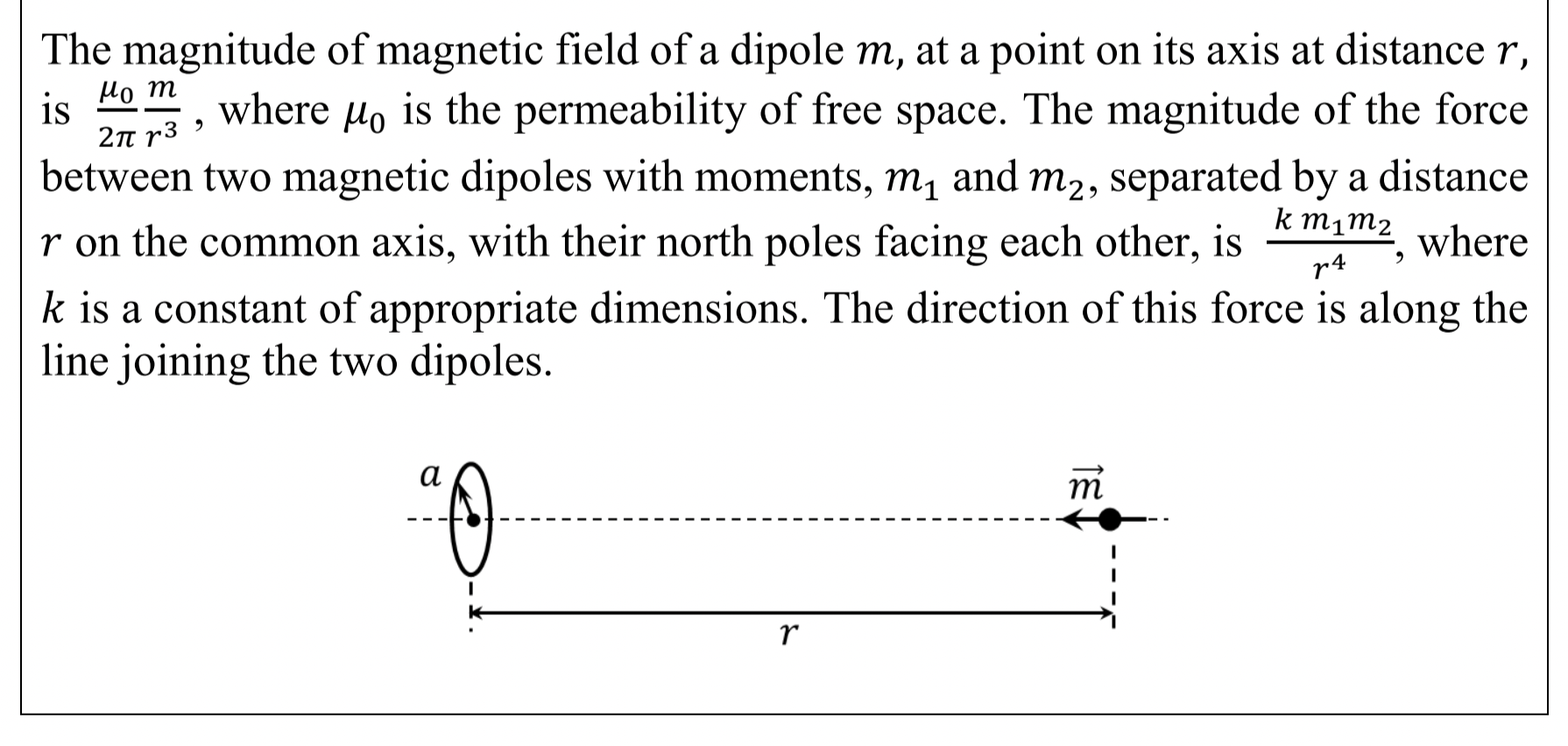
You will need magnetic field at center of a loop by current in the loop to be \(\mu_0 I/ 2 a \text{.}\)
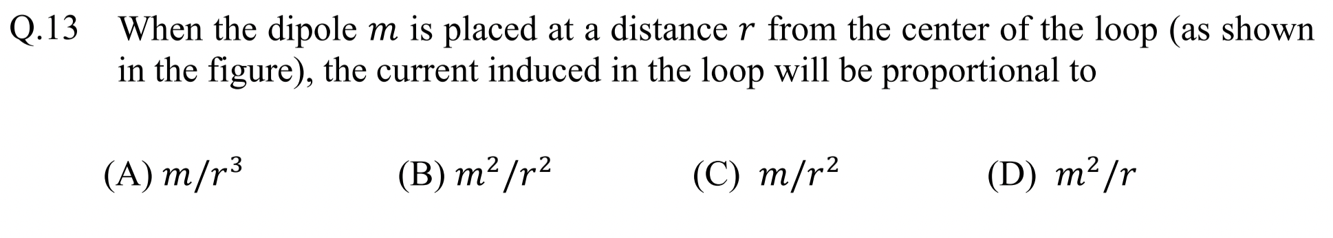
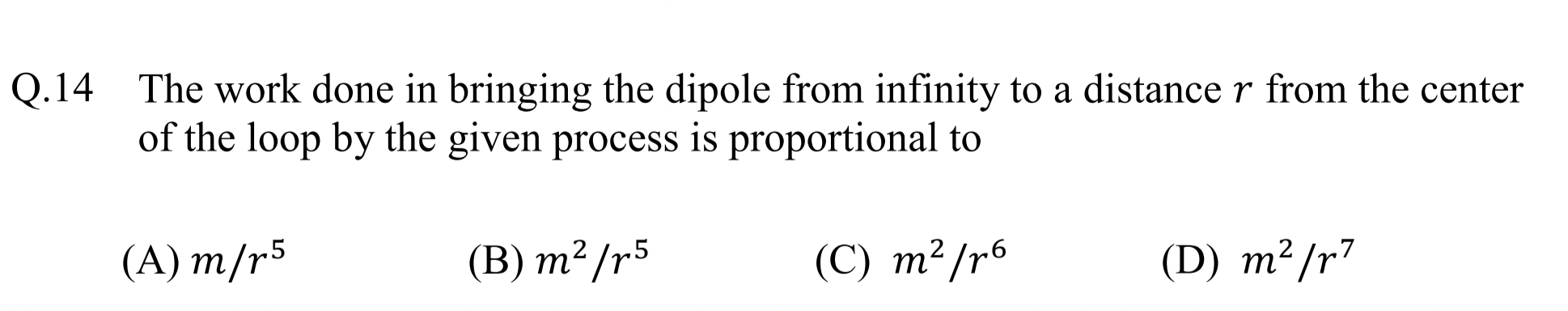
Q13: (A), Q14: (C).
Figure 1.2.17 shows magnetic field lines by the magnetic dipole and induced current in the loop.
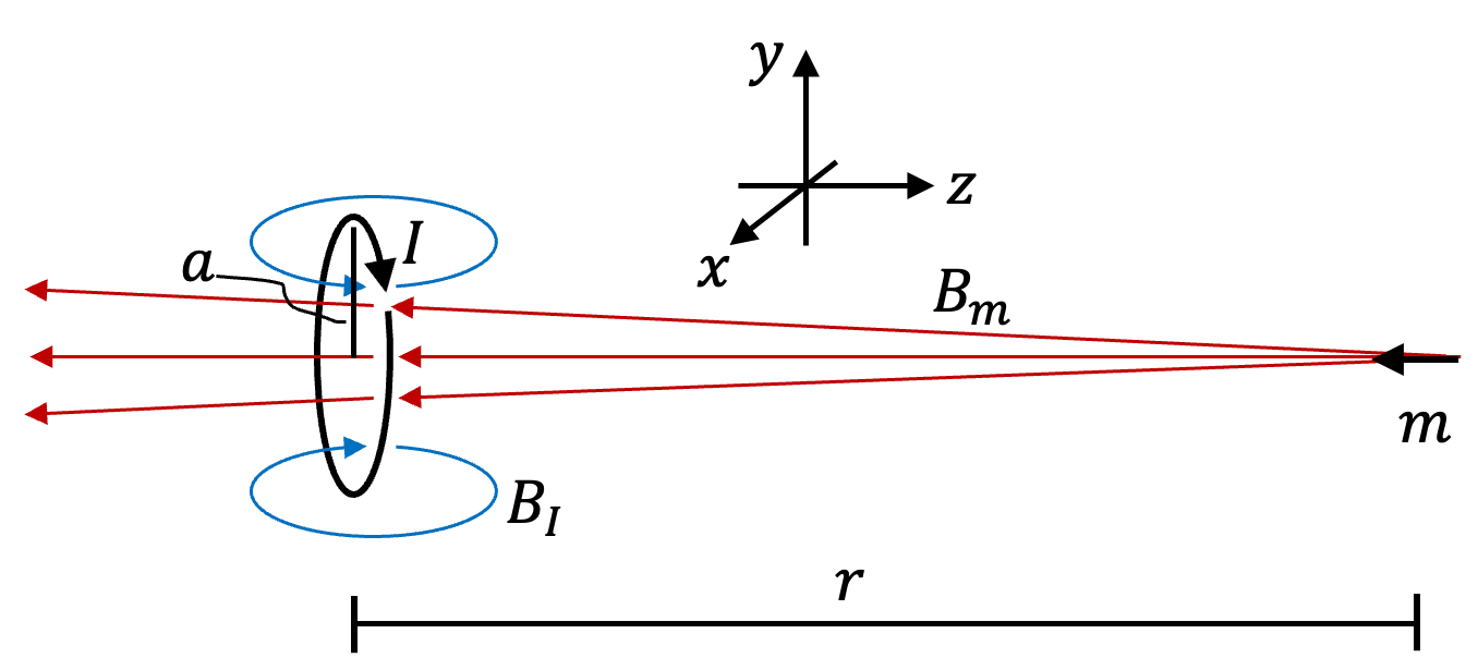
Magnetic field at the center of the loop by current \(I\) in the loop can be computed by Biot-Savart law easily to be
Magnetic field by the dipole at the center is given in the problem.
Assuming loop to be small, we can assume \(\vec B_\text{I}\) and \(\vec B_\text{m}\) at other points of the loop be same as at the center. Therefore, canceling of the flux through the loop will give us
Therefore,
Therefore, answer to Q13 is (A).
Let us fix loop at origin and bring dipole from \(z=\infty\) to \(z=r\text{,}\) balancing the magnetic force between the loop and the dipole by an applied force \(\vec F\) at each instant. Making use of the formula for magnetic force is given in the problem statement, we will need following force when dipole is at \(z\text{.}\)
where \(m_1=m\) and \(m_2\) due to current \(I\) in loop depends on separation \(z\) by
The negative sign in force is for the direction of applied force being towards negative \(z\)-axis since magnetic force would be repulsive and pointed towards positive \(z\)-axis. Now, we find work by performing the work integral.
Therefore, answer for Q14 is (C).
Problem 1.2.18. Q15 and Q16: Thermodynamics.
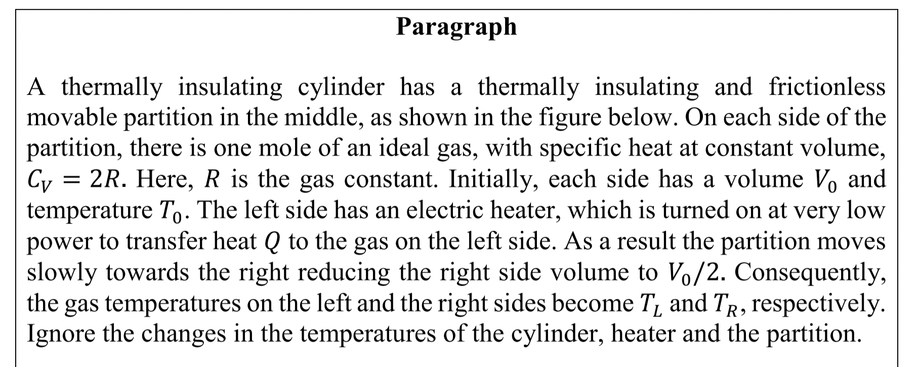
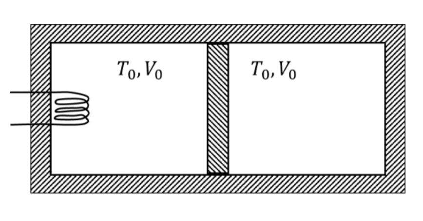
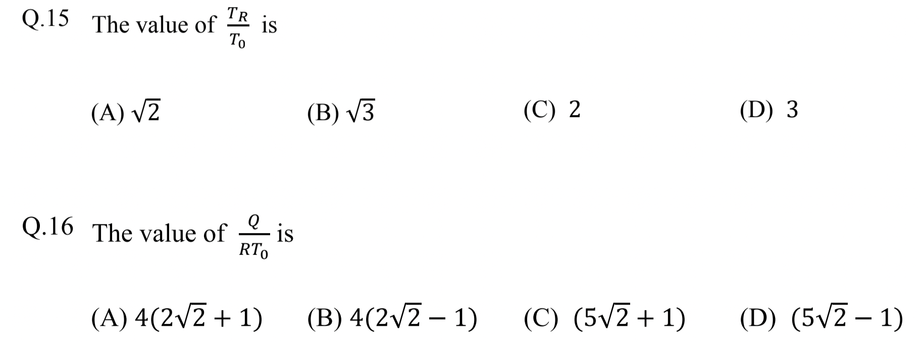
For Q15, examine the adiabatic process of the right side. For Q16, think of the combined system's energy.
Q15: (A), Q16: (B).
To find \(T_R/T_0\text{,}\) we can use the fact that right side undergoes an adiabatic process. Therefore,
The second relation immediately gives
Here \(V_i/V_f = 2\) and \(\gamma = C_P/C_V\) with \(C_P = C_V+1 = 3\text{.}\) Therefore
Thus, answer for Q15 is (A).
For this part, we can think of the two parts as one system. That system interacts with the external world though \(Q\) from the heater. Thus, change in internal energy of the two sides must be all due to this \(Q\text{.}\)
Therefore,
We need to figure out \(T_L/T_0\) and use it in this formula. Since moving partition is free to move, the pressure on the two sides must be same. Hence, at the end, pressure on the left will equal pressure at the right, which can be obtained from \(V_R\) and \(T_R\text{.}\)
Now, using \(p_L\) and \(V_L= \frac{3}{2}V_0\text{,}\) we get
Using this, \(T_R/T_0=\sqrt{2}\) derived earlier, \(C_v=2R\text{,}\) and \(n_L=n_R=1\) in Eq. (1.2.15) we get
Therefore, answer for Q16 is (B).
Problem 1.2.19. Q17: Null Bridge Circuit.
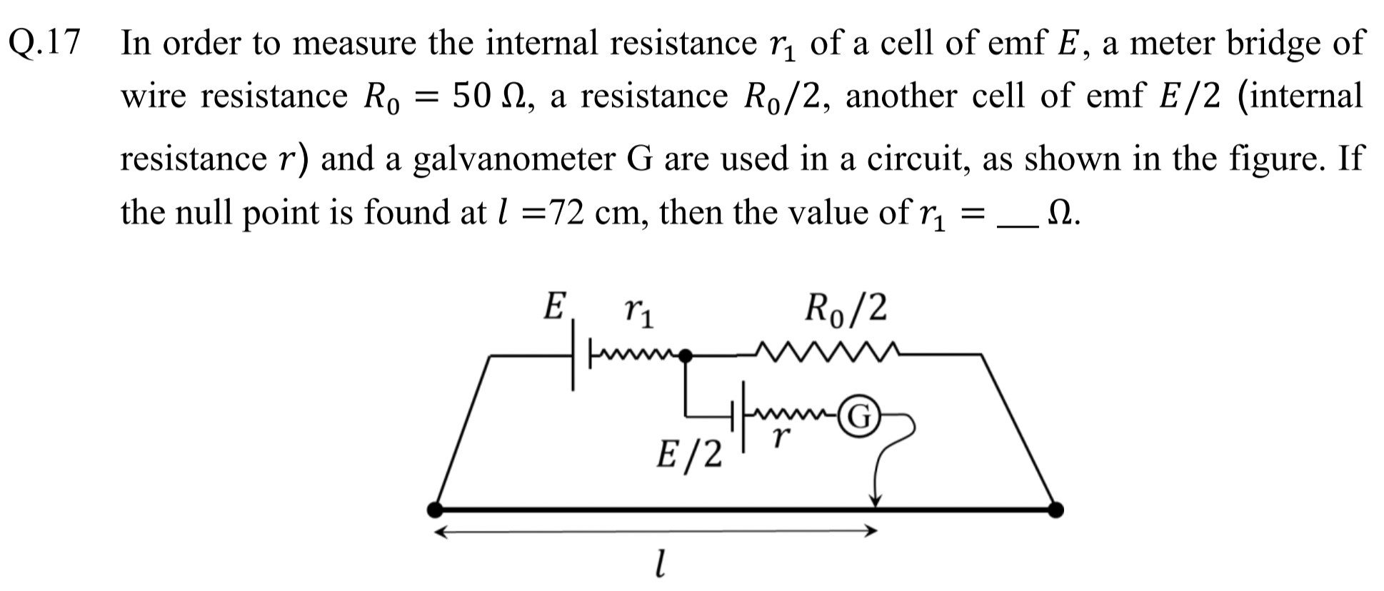
Null condition means current through G is zero.
\(3\,\Omega\)
We label the circuit with currents \(I_1\) and \(I_2\text{,}\) and voltage points of interest as shown in Figure 1.2.20 .
The null condition means no current in the branch that has the galavanometer G., i.e., \(I_2=0\text{.}\) We will choose ground at point a.
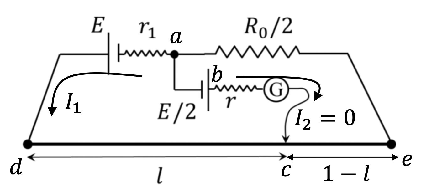
From a-d-e-a loop we get
From a-b-c-e-a loop we get
We get \(I_1\) from this second equation and plug that into the first equation above to get \(r_1\text{.}\)
Into Eq. (1.2.16),
Problem 1.2.21. Q18: Two-body System.
Use dynamics of reduced mass.
\(n=9\text{.}\)
A two-body problem in which each body goes around CM in a circle, we can show that a fictitious particle of reduced mass \(\mu\) will go in a circular orbit with radius equal to their separation distance and same period as the periods of the two bodies around the CM, and another fictitious particle of total mass \(M\) placed at the center.
Using \(v = \omega r\) for speed, we will have the following equation of motion of the fictitious particle.
Canceling \(\mu\text{,}\) and writing \(\omega = 2\pi/T\text{,}\) we get
On the other hand, for Earth we have
Taking the ratio we get
Since \(n=T/T_E\text{,}\) this gives \(n=9\text{.}\)
Problem 1.2.22. Q18: Photoelectric Effect.
Use energy conservation equation for photoelectric effect.
\(6.0\text{ eV}\text{.}\)
In photoelectric effect, incident photon energy \(E_\gamma=hf\text{,}\) work function \(\Phi\text{,}\) and maximum kinetic energy of emitted electron \(K_\text{max}\) are related by energy conservation.
From the given data on P and Q, we can say that
Using the numerical data, this gives
Therefore,
Now, from data on R we have