Section 44.9 AC Circuits Bootcamp

Subsection 44.9.1 AC Circuit Elements

Subsection 44.9.2 Power in AC Circuits

Subsection 44.9.3 AC Circuits Using Complex Numbers

Subsection 44.9.4 Transformers

Subsection 44.9.5 Miscellaneous

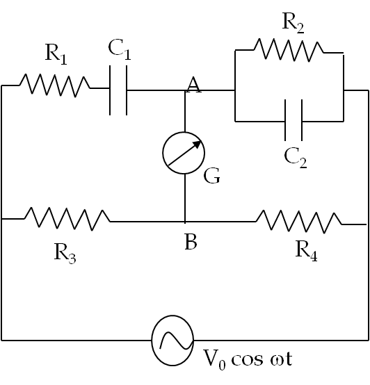
RC oscillators commonly use a Wein bridge circuit shown in Figure 44.9.20. A galvanometer G is connected between the points marked A and B to detect any current flow between A and B. The Wein bridge circuit is said to be balanced when no current flows between A and B.

Figure 44.9.20. For Problem 44.9.19.

Prove that the following relations must hold true when the circuit is balanced.

\begin{align} \amp \frac{R_1}{R_2} + \frac{C_1}{C_2} = \frac{R_3}{R_4},\tag{44.9.1}\\ \amp \omega = \frac{1}{\sqrt{R_1 R_2 C_1 C_2}}.\tag{44.9.2} \end{align}
Hint

Replace passive elements by their complex impedances.

Answer

already in statement.

Solution

Let us replace the resistors and capacitors by their complex impedances. Suppose current \(I_1\) flows in the upper branch and \(I_2\) in the lower branch - note that the current through G is zero at the balance. Now, we write the Kirchhoff's loop rules for the loop on the left of the galvanometer G and the loop on the right of G for the condition that there be no current through G. This

\begin{align*} \amp I_1 \left( R_1 - \dfrac{i}{\omega C_1} \right) = I_2 R_2,\\ \amp I_1 \left[\dfrac{R_2\times \frac{-i}{\omega C_2}}{R_2 - \frac{i}{\omega C_2}} \right] = I_2 R_2. \end{align*}

Dividing out \(I_1\) and \(I_2\) gives the following complex equation.

\begin{equation*} \dfrac{(\omega R_1 C_1 -i)(\omega R_2 C_2 - i)}{-i\omega C_1 R_2} = \dfrac{R_3}{R_4}. \end{equation*}

Separating out the real and imaginary parts of this equation gives

\begin{align*} \amp \omega^2 R_1 C_1 R_2 C_2 -1 = 0,\\ \amp \omega(R_1 C_1 + R_2 C_2) = \dfrac{R_3}{R_4}\:R_2 \omega C_2. \end{align*}

These equations yield the results we seek.

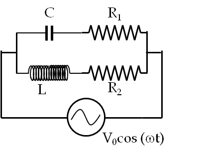
A cross-over circuit is used deliver power to two different parts of the circuit depending on the frequency of the driving signal. For instance one would want more power be delivered to woofer at low frequency and to tweeter at high frequency.

For given \(L\text{,}\) \(C\text{,}\) \(R_1\) and \(R_2\) in the circtuin in Figure 44.9.22, find the cross-over frequency such that below that frequency more power goes to \(R_2\) and above that frequency more power goes to \(R_1\text{.}\)

Figure 44.9.22. For Problem 44.9.21.
Hint

Use complex analysis.

Answer

See solution.

Solution

Let \(Z_1\) and \(Z_2\) be the complex impedances of the upper and lower branches respectively.

\begin{align*} \amp Z_1 = R_1 - \dfrac{i}{\omega C},\ \ |Z_1| = \sqrt{R_1^2 + \dfrac{1}{\omega^2 C^2}},\\ \amp Z_2 = R_2 - i \omega L,\ \ |Z_2| = \sqrt{R_2^2 + \omega^2 L^2}. \end{align*}

The amplitudes of the currents in the two branches will be

\begin{align*} \amp I_{10} = \dfrac{V_0}{|Z_1|},\\ \amp I_{20} = \dfrac{V_0}{|Z_2|}. \end{align*}

Equating the power in the two resitors will give us a condition for the cross-over frequency \(\omega\text{.}\)

\begin{equation*} \dfrac{1}{2}I_{10}^2\:R_1 = \dfrac{1}{2}I_{20}^2\:R_2. \end{equation*}

Therefore,

\begin{equation*} \dfrac{R_1}{|Z_1|^2} = \dfrac{R_2}{|Z_2|^2}. \end{equation*}

This gives a quartic equation in \(\omega\text{,}\) which student is encouraged to solve. I found the following answer for the positive real \(\omega\text{.}\)

\begin{align*} \omega = \amp \dfrac{1}{\sqrt{2}\;LC}\left[\left(R_1R_2 - R_2^2\right)C^2 + \sqrt{\left(R_2^2-R_1R_2\right)^2C^4 + \dfrac{4 R_2L^2C^2}{R_1}} \right]. \end{align*}