A network of electrical devices connected together is called a circuit. A conductor used in a circuit that has a significant resistance is also called a resistor. When a circuit has only resistors and voltage sources, such as batteries, then the circuit is also called a resistive circuit. We will study circuits in which the potential difference between the terminals of the voltage sources does not change with time. These circuits are called direct-current (DC) circuits.
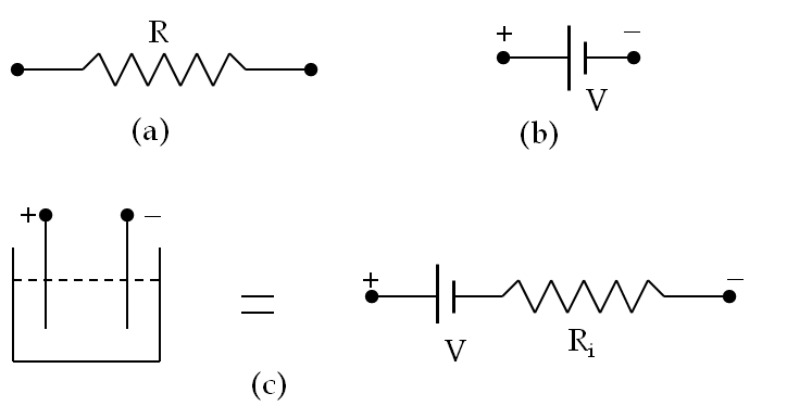
In a circuit diagram, a voltage source is usually represnted by two parallel unequal lines, with the higher potential end, i.e., the postitive terminal at longer line, and a resistor is represented by a saw tooth line as shown in Figure 34.25. We label circuit elements with values relevant to them, e.g., source is labeled with the voltage value and a resistor with the value of resistance.
Often batteries and other constant-voltage sources have significant resistance themselves, which adds to the total resistance of the circuit. The resitance of a source is also called the internal resistance. If the internal resistance is a significant factor in the circuit, we would include an internal resistance in the model as given in Figure 34.25(c), otherwise we will tend to ignore them.
Figure34.25.Representating circuit elements: (a ) resistor, (b) DC voltage source, and (c) an electrolytic DC voltage source with internal resistance. Voltage source is labeled with a voltage value that give the potential difference between the two terminals, \(\Delta \phi = \phi_+ - \phi_- = V\text{.}\) The resistor is labeled with the value of resistance.
Subsection34.5.1A Simple DC Circuit
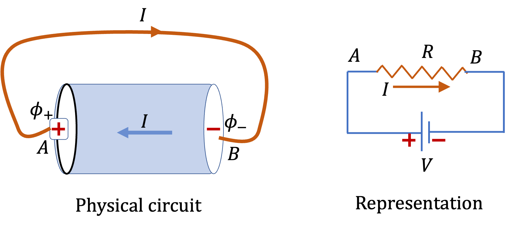
When you connect a wire of resistance \(R\) to the two terminals of a battery of constant voltege \(V\text{,}\) as shown in Figure 34.26 you create potential difference across the resistor, whose value is \(V\text{.}\)
Figure34.26.A wire of resistance \(R\) is connected across the terminals of a battery of voltage \(V\text{.}\) The potential drop across the resistor is \(\Delta \phi = V\text{.}\) Ohm’s law applied to the wire gives current through the wire as \(I = V/R\text{.}\)
When we apply Ohm’s law to the resistor, we will get the following relation.
\begin{equation*}
\Delta \phi = I R.
\end{equation*}
Using Eq. (34.16) we get the following relation between the voltage of the battery and current through the wire.
\begin{equation}
V = I R.\tag{34.17}
\end{equation}
Now, we note that current is moving charges in the wire. Where do they go? Since charges are not accumulating anywhere, charges must flow at the same rate inside the battery. Therefore, the current here is also current through the battery.
The current through the single voltage source is also called overall current of the circuit.
In the following sections we will use Ohm’s law to analyze a few useful simple circuits that have only one voltage source. Basically, there are four types of simple resistive circuits with multiple resistors connected to a single voltage source:
Circuits with resistors connected in series.
Circuits with resistors connected in parallel.
Circuits with resistors connected neither in series nor in parallel but they could be simplified by series/parallel methods.
Bridge circuits which cannot be simplified by series/parallel methods.
In each circuit, we will be interested in determining the current through each resistor and voltage values at all nodes. Once we have determined these quantities for each resistor, we can find the power dissipated in the resitors and the energy used by them.
Example34.27.Current and Electric Field in a Wire Connected Across a Battery.
A very long wire of resistance \(2.5\,\Omega\) is attached across a \(1.5\,\text{V}\) battery. (a) What is the current through the wire? (b) If the length of the wire is \(10.0\,\text{m}\) and if the electric field has constant magnitude in the wire, find the electric field.
Solution1.a
By using voltage drop and resistance, we wimmediately get the current.
\begin{equation*}
I = \frac{V}{R} = \frac{1.5}{2.5} =0.6\,\text{A}.
\end{equation*}
Solution2.b
Since electric field is constant, the relation between electric field in the wire and the potential difference between the ends of the wire will be simply
\begin{equation*}
E L = |\Delta\phi|
\end{equation*}
Therefore,
\begin{equation*}
E = \frac{1.5\,\text{V}}{10\,\text{m}} = 0.15\,\text{V/m}.
\end{equation*}