
Section 9.9 Rotational Second Law

You already know that, if mass is not changing, then, acceleration is proportional to the force on the body.

\begin{equation} m\,\vec a = \vec F_{\text{net}}\ \ \ \ (m \text{ not changing})\label{eq-rotational-second-law-f-equal-ma}\tag{9.9.1} \end{equation}

We will show below that this law leads to the following equation for fixed-axis-rotation about a principal axis of a rigid body of moment of inertia \(I\) about the axis of interest, net torque \(\mathcal{T}_{\text{net,ext}}\) from external forces, and angular acceleration \(\alpha\text{.}\)

\begin{equation} I\,\alpha = \mathcal{T}_{\text{net,ext}}, \ \ \ \ (I \text{ not changing}).\label{eq-rotational-second-law-tau-equal-Ialpha}\tag{9.9.2} \end{equation}

The requirement that moment of inertia not change with time restricts the applicability of this equation to rigid bodies whose shape and mass distribution are fixed in time.

To find the magnitude and direction of the net torque, we need to think of each torque as a vector with the direction either as positive \(z \) axis or negative \(z \) axis with \(z \) axis being the axis of rotation, or, as couterclockwise or clockwise sense of rotation.

Since \(I \) is a positive number, the direction of the angular acceleration \(\alpha\) is the same as the direction of the net torque \(\vec{\mathcal{T}}_{\text{net}} \text{.}\)

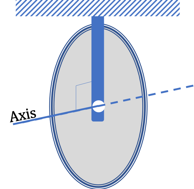
A \(20\text{-kg}\) pulley of radius \(10\text{ cm}\) has a rope wound around its edge. When the rope is pulled with some force the pulley begins to rotate. (a) Where is the axis of rotation in this problem? (b) Is the axis of rotation fixed in time?

Figure 9.9.2.

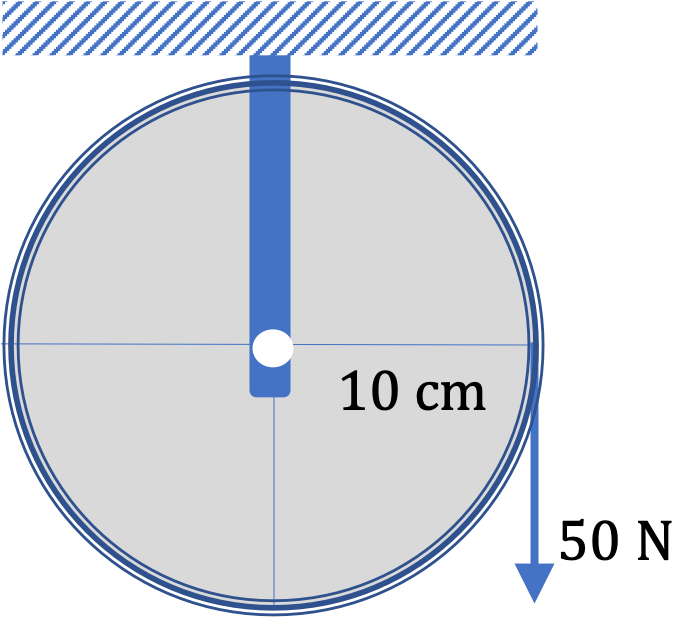
(c) Is the rotating body a rigid body? (d) What will be the angular acceleration of the pulley when the force in the rope is \(50\text{ N}\) down as shown in the figure.

Hint

(a) Think of how the disk is rotating. (b) Same hint as (a). (c) Is the shape of the body changing? (d) Find \(I \) first.

Answer

(a) Through the center and perpendicular to the surface of the pulley, (b) Yes, fixed, (c) With the mass of the rope negligible, the pulley+rope wound around it is a rigid body, (d) \(50\text{ rad/sec}^2\text{,}\) clockwise or towards into-the-page.

Solution 1 (a)

(a) The axis of rotation is the imaginary line that passes through the center of the pulley and is perpendicular to the disk of the pulley.

Figure 9.9.3.

Solution 2 (b)

(b) Yes, the axis is fixed.

Solution 3 (c)

(c) The pulley is the rotating body. The rope on eht pulley is also rotating. So, in a sense, the rotating body is losing some of its mass. But, we will assume that mass of the rope is negligible. With that assumption, the roating body is a rigid body.

Solution 4 (d)

(d) Magnitude:

Since we have a rigid body rotating about a fixed axis, we can use

\begin{equation*} I\alpha = \mathcal{T}_{\text{net}}. \end{equation*}

Here, \(I \) is the moment of inertia of the pulley, which we can consider to be a disk.

\begin{equation*} I = \dfrac{1}{2}\, MR^2. \end{equation*}

By drawing a diagram, you can convince yourself that the lever arm of the tension force is just the radius of the pully. Therefore

\begin{equation*} \mathcal{T}_{T} = R T. \end{equation*}

Lines of other forces on the pulley pass through the axis, therefore, their lever arms are zero. This gives us the net toque to be

\begin{equation*} \mathcal{T}_{\text{net}} = RT. \end{equation*}

Therefore, the angular acceleration is

\begin{equation*} \alpha = \dfrac{\mathcal{T}_{\text{net}}}{I} = \dfrac{ 2T}{MR} = \dfrac{ 2\times 50}{20\times 0.10} = 50\text{ rad/sec}^2. \end{equation*}

Direction:

The direction of the net torque is into-the-page, which is the same as negative \(z \) axis or the clockwise rotation. This is the same direction for the angular acceleration.

Consider a wheel of mass \(M\) and radius \(R \) that is free to rotate about an axle through its center. Several turns of a thin light non-sticky tape, whose mass can be neglected, are wound at the edge.

A block of mass \(m \) is attached to the free end of the tape as shown in Figure 9.9.5. When the block is released, the tape unwinds smoothly and the wheel rotates. Assume the friction on the wheel at the axle is negligible.

Figure 9.9.5.

Find the angular acceleration of the wheel and the tension in the tape. Its preferable that you find the answer in symbols, but if you are not yet comfortable doing calculations with symbols, you can use the following numbers: \(M = 20\text{ kg}\text{,}\) \(R = 0.25\text{ m}\text{,}\) \(m = 2.5\text{ kg}\text{.}\)

Hint

Set up two equations: (1) rotation of the wheel and (2) translation motion of the block. Also, the force of tension is not equal to \(mg \text{.}\)

Answer

\(\alpha = \left( \dfrac{2m}{2m + M} \right)\ \dfrac{g}{R}, \) \(T = \left( \dfrac{m}{2m + M}\right)\ Mg, \) \(\alpha = 7.85\text{ rad/s}^2\text{,}\) \(T = 19.6\text{ N}\text{.}\) The direction of the angular acceleration is into-page, or negative \(z \) axis, or clockwise sense. The direction of tension is down when acting on the wheel and up when acting on the block.

Solution

Here the translational motion of the block and the rotational motion of the wheel are coupled. For every radian of rotation, the tape unwinds by a distance \(R \) as given by the arc-radius-angle formula of a circle. Therefore, every radian of rotation is accompanied by a vertical displacement of the block by \(R\text{.}\) More generally, for an angular displacement of \(\theta\) radians of the wheel, the vertical displacement of the block is \(R\theta\text{.}\)

The coupling of motion causes the following equality between the magnitudes of the acceleration, \(a \text{,}\) of the block and the angular acceleration, \(\alpha\text{,}\) of the wheel.

\begin{equation*} a = R\, \alpha.\ \ \text{(both sides positive.)} \end{equation*}

Now, we write the equation of motion for the block. Here \(mg \gt T\) by \(ma \text{.}\)

\begin{equation*} mg - T = ma, \end{equation*}

in which we can replace \(a\) to get

\begin{equation} \ mg-T=mR\alpha.\label{eq-block-attached-to-unwinding-tape-may-T-mg}\tag{9.9.3} \end{equation}

Figure 9.9.6.

For the rotation of the wheel around its axle, we can ignore all forces that go through the axis. We also ignore the friction at the radius of the axle, as instructed. Then, there is only the force of tension, which acts down when acting on the wheel. The magnitude of torque is related to the magnitude of the angular acceleration by

\begin{equation*} RT = \left( \dfrac{1}{2} MR^2\right)\, \alpha,. \end{equation*}

Figure 9.9.7.

This gives us the following for magnitude of tension.

\begin{equation} T = \dfrac{1}{2} MR \, \alpha.\label{eq-block-attached-to-unwinding-tape-I-alpha-RT}\tag{9.9.4} \end{equation}

From Eqs. (9.9.3), and (9.9.4), we get the magnitudes of the angular acceleration and tension force to be

\begin{align*} \amp \alpha = \left( \dfrac{2m}{2m + M} \right)\ \dfrac{g}{R}, \\ \amp T = \left( \dfrac{m}{2m + M}\right)\ Mg. \end{align*}

The direction of the angular acceleration is into-page, or negative \(z \) axis, or clockwise sense. The direction of tension is down when acting on the wheel and up when acting on the block.

Using the values \(M = 20\text{ kg}\text{,}\) \(R = 0.25\text{ m}\text{,}\) \(m = 2.5\text{ kg}\text{,}\) we find the values of magnitudes to be.

\begin{equation*} \alpha = 7.85\text{ rad/s}^2,\ \ T = 19.6\text{ N}. \end{equation*}

In an Atwood machine two blocks connected by a light string hang from the two sides of a pulley without the string sliding over the pulley. Instead, the string is assumed to unwind smoothly.

Suppose the pulley is frictionless at the axle, but the mass of the pulley is not negligible compared to the masses of the blocks.

Let \(M \) and \(R \) be the mass and radius of the pulley, which, for purposes of moment of inertia, can be assumed to be a uniform disk, and \(m_1 \) and \(m_2 \) be the masses of the two blocks.

Figure 9.9.9.

I would prefer you do the problem in symbols. But, if you want numbers, use the following:

\begin{equation*} M = 20\text{ kg}, m_1 = 10\text{ kg}, m_2 = 5\text{ kg}, R = 0.25\text{ m}. \end{equation*}

(a) Find the following five quantities:

  1. Tension in the string on the the side of the pulley that has block 1,
  2. Tension in the string on the the side of the pulley that has block 2,
  3. Acceleration of block 1,
  4. Acceleration of block 2, and
  5. Angular acceleration of the pulley.

(b) What happens to the tensions if mass of the pulley is negligible, i.e., \(M = 0\text{?}\)

Hint

(a) Set up three equations - one for \(m_1\text{,}\) another for \(m_2 \) and the third for pulley, and use the constraint \(a = R\alpha\text{.}\) (b) If you do the problem in symbols, you can just set \(M=0\text{.}\)

Answer

(a) \(a = \dfrac{2(m_1 - m_2)\, g}{2m_1 + 2m_2 + M}\text{,}\) \(\alpha = a /R \text{,}\) \(T_1 = \left( \dfrac{4m_2 + M}{2m_1 + 2 m_2 + M} \right)\, m_1 g\text{,}\) \(T_2 = \left( \dfrac{4m_1 + M}{2m_1 + 2 m_2 + M} \right)\, m_2 g\text{.}\) Numerical: \(a = 1.98\text{ m/s}^2, \) \(\alpha = 7.85\text{ rad/s}^2, \) \(T_1 = 78.5\text{ N},\) \(T_2 = 58.9\text{ N}.\) (b) They become equal in magnitude.

Solution 1 (a)

We have solved a similar problem before by assuming that the pulley was massless and frictionless. These assumptions about the pulley let us assert that the tensions on the two sides had the same magnitude. Here, we cannot make this assumption. We will see below that the equation of rotation of the pulley will become inconsistent if we assume that the tensions on the two sides have the same magnitude.

Let \(T_1 \) and \(T_2 \) be the magnitudes of the tension force on the two sides of the pulley.

The motion of the blocks are connected by the unchanging length of the string. This makes the magnitude of their accelrations equal. Thus, we use same symbol \(a \) for the magnitude of their accelerations. That is,

\begin{equation*} a_1 = a = a_2.\ \ \ (\text{magnitudes, only}) \end{equation*}

Since the string going over the pulley is not slipping, the length by which the string will unwind, i.e., the distance either of the blocks moves, is related to the angular displacement of the pulley by the arc-radius-angle relation. This gives the following relation between the magnitude of the angular acceleration, \(\alpha\) and the magnitude of the acceleration, \(a \text{,}\) of the blocks.

\begin{equation} a = R\,\alpha.\label{eq-atwood-machine-a-R-alpha}\tag{9.9.5} \end{equation}

Now, we set up free-body diagrams for the two blocks to write their \(\vec F = m\vec a\text{.}\) For concreteness, let us assume that the acceleration of block 1 is pointed down, which will autimatically make the acceleration of block 2 up.

Using the free-body diagrams we will get the following two equations.

\begin{align} \amp m_1 g - T_1 = m_1 a, \label{eq-atwood-machine-m1g-T1-m1a}\tag{9.9.6}\\ \amp T_2 - m_2 g = m_2 a. \label{eq-atwood-machine-m2g-T2-m2a}\tag{9.9.7} \end{align}

Let positive \(z \) axis be pointed out-of-page. Then, the torque by force \(\vec T_1 \) is pointed in the positive \(z \) direction and that by \(\vec T_2 \) is pointed in the negative \(z \) direction. Therefore, they will oppose each other. The lines of other forces on the pulley, such as gravity and normal, pass though the axis, so they do not contribute to the net torque. Thus, we get the following equation for the rotational motion of the pulley.

\begin{equation*} RT_1 - RT_2 = \left( \dfrac{1}{2} MR^2\right)\, \alpha, \end{equation*}

which we can simplify by replacing \(\alpha = a/R\) to the following.

\begin{equation} T_1 - T_2 = \dfrac{1}{2} Ma.\label{eq-atwood-machine-T1-T2-half-Ma}\tag{9.9.8} \end{equation}

Adding equations (9.9.6), (9.9.7), and (9.9.8), we get the following after some simplification.

\begin{equation*} a = \dfrac{2(m_1 - m_2)\, g}{2m_1 + 2m_2 + M}, \end{equation*}

which also gives us \(\alpha\) by \(a = R\alpha \text{.}\)

\begin{equation*} \alpha = \dfrac{1}{R}\ \dfrac{2(m_1 - m_2)\, g}{2m_1 + 2m_2 + M}, \end{equation*}

By using \(a \) in Eq. (9.9.6), we get \(T_1 \) and in Eq. (9.9.7), we get \(T_2\text{.}\)

\begin{align} \amp T_1 = \left( \dfrac{4m_2 + M}{2m_1 + 2 m_2 + M} \right)\, m_1 g,\label{eq-atwood-machine-T1-final}\tag{9.9.9}\\ \amp T_2 = \left( \dfrac{4m_1 + M}{2m_1 + 2 m_2 + M} \right)\, m_2 g,\label{eq-atwood-machine-T2-final}\tag{9.9.10} \end{align}

If you use the numerical values, you should get

\begin{align*} \amp a = 1.98\text{ m/s}^2,\ \ \alpha = 7.85\text{ rad/s}^2, \\ \amp T_1 = 78.5\text{ N}, \ \ T_2 = 58.9\text{ N}. \end{align*}
Solution 2 (b)

(b) Setting \(M=0\) in the formulas in Eqs. (9.9.9) and (9.9.10), immediately shows that the two tensions are equal.

\begin{equation*} T_1 = T_2 = 2\ \left( \dfrac{m_1m_2}{m_1 + m_2 } \right)\ g = 65.4\text{ N}. \end{equation*}

Subsection 9.9.1 (Calculus) Derivation of the Rotational Second Law

Consider a simple system of one particle of mass \(m\) with velocity \(\vec v \) at a position \(\vec r \) from the axis. Suppose one force \(\vec F \) acts on the particle. The momentum \(\vec p \) of the particle \(\vec p = m\vec v \) obeys Newton's second law of motion given by

\begin{equation} \dfrac{d\vec p}{dt} = \vec F.\tag{9.9.11} \end{equation}

Figure 9.9.10.

The angular momentum \(\vec L\) of the particle is

\begin{equation} \vec L = \vec r \times \vec p.\tag{9.9.12} \end{equation}

Now, let us investigate the rate at which angular momentum changes.

\begin{align*} \dfrac{d\vec L}{dt} \amp =\dfrac{d (\vec r \times p)}{dt}\\ \amp =\dfrac{d \vec r }{dt}\times \vec p + \vec r \times\dfrac{d \vec p }{dt} = \vec v\times \vec p + \vec{\mathcal{T}}, \end{align*}

where \(\vec{\mathcal{T}} \) is the torque. The term \(\vec v\times \vec p \) is zero since the angle between \(\vec v \) and \(\vec p\) is zero and hence their vector product is zero. Therefore, we get the second law for rotation in terms of rate of change of angular momentum.

\begin{equation} \dfrac{d\vec L}{dt} = \vec{\mathcal{T}}.\label{eq-rotational-second-law-L-equals-tau}\tag{9.9.13} \end{equation}

We can convert this to \(I \alpha = \mathcal{T} \) in the case of fixed-axis-rotation about a principal axis. In that case, the direction of \(\vec L\) is fixed, and the magnitude is given by

\begin{equation*} L = I\, \omega. \end{equation*}

Therefore, Eq. (9.9.13) for constant \(I \) becomes

\begin{equation*} I\, \dfrac{d\omega}{dt} = \mathcal{T}. \end{equation*}

Since \(\dfrac{d\omega}{dt} \) is the angular acceleration, this is just

\begin{equation*} I\, \alpha = \mathcal{T}. \end{equation*}

We will study modification of this relation in the next chapter when we relax the condition of fixed axis.

Subsection 9.9.2 (Calculus) Rotational Second Law for Multiparticle System

First we consider a simple two-particle system. Let particle 1 has external force \(\vec F_1^{\text{ext}} \) and internal force from the second particle \(\vec F_{12}^{\text{int}} \text{.}\) Similarly, let particle 2 has external force \(\vec F_2^{\text{ext}} \) and internal force from the second particle \(\vec F_{21}^{\text{int}} \text{.}\) Note the following relation from Newton's third law.

\begin{equation} \vec F_{12}^{\text{int}} = - \vec F_{21}^{\text{int}}.\label{eq-rotational-second-law-internal-forces}\tag{9.9.14} \end{equation}

Let \(\vec r_1\) be the position of particle 1 and \(\vec r_2\) be the position of particle 2. Further, let \(\vec L_1\) be the angular momentum of particle 1 and \(\vec L_2\) be the angular momentum of particle 2. Then, we can write rotational second law for the two particles as

\begin{align*} \amp \dfrac{d\vec L_1}{dt} = \vec r_1 \times \vec F_1^{\text{ext}} + \vec r_1 \times\vec F_{12}^{\text{int}}, \\ \amp \dfrac{d\vec L_2}{dt} = \vec r_2 \times\vec F_2^{\text{ext}} + \vec r_2 \times\vec F_{21}^{\text{int}}, \end{align*}

Adding these two equations, we find that the net angular momentum changes as

\begin{equation*} \dfrac{d\vec L_{\text{net}}}{dt} = \vec{\mathcal{T}}_{\text{net,ext}} + (\vec r_1 - \vec r_2)\times \vec F_{12}^{\text{int}}. \end{equation*}

Notice that the vector \((\vec r_1 - \vec r_2) \) is a vector pointed from particle 2 towards particle 1. Therefore, if the internal force between the two particles are either attractive or repulsince acting along the line joining the two particles, then the last term will be zero.

\begin{equation*} (\vec r_1 - \vec r_2)\times \vec F_{12}^{\text{int}} = 0. \end{equation*}

Therefore, we find that total angular momentum changes in response to only external torques.

\begin{equation} \dfrac{d\vec L_{\text{net}}}{dt} =\vec{\mathcal{T}}_{\text{net,ext}}.\tag{9.9.15} \end{equation}

For fixed-axis rotation, the direction of axis of rotation is fixed in time. If we choose \(z \) axis to be the axis of rotation, then we deal with only the \(z\) component of the angular momentum.

\begin{equation} \dfrac{d L_z^{\text{net}} }{dt} = \mathcal{T}_{\text{net},z}.\tag{9.9.16} \end{equation}

Now, if the axis is a symmetry axis, the angular momentum is

\begin{equation*} L_z^{\text{net}} = I\, \omega. \end{equation*}

With \(\alpha = \dfrac{d\omega}{dt}\text{,}\) we arrive at

\begin{equation} I\, \alpha = \mathcal{T}_{\text{net},z}.\tag{9.9.17} \end{equation}