Example 34.37. A Current Divider.
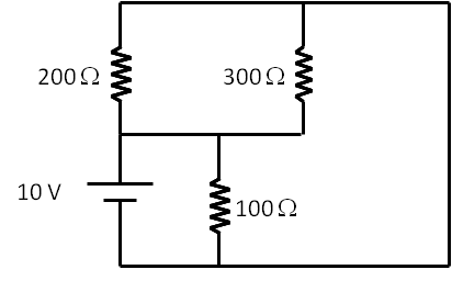
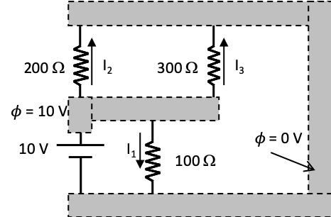
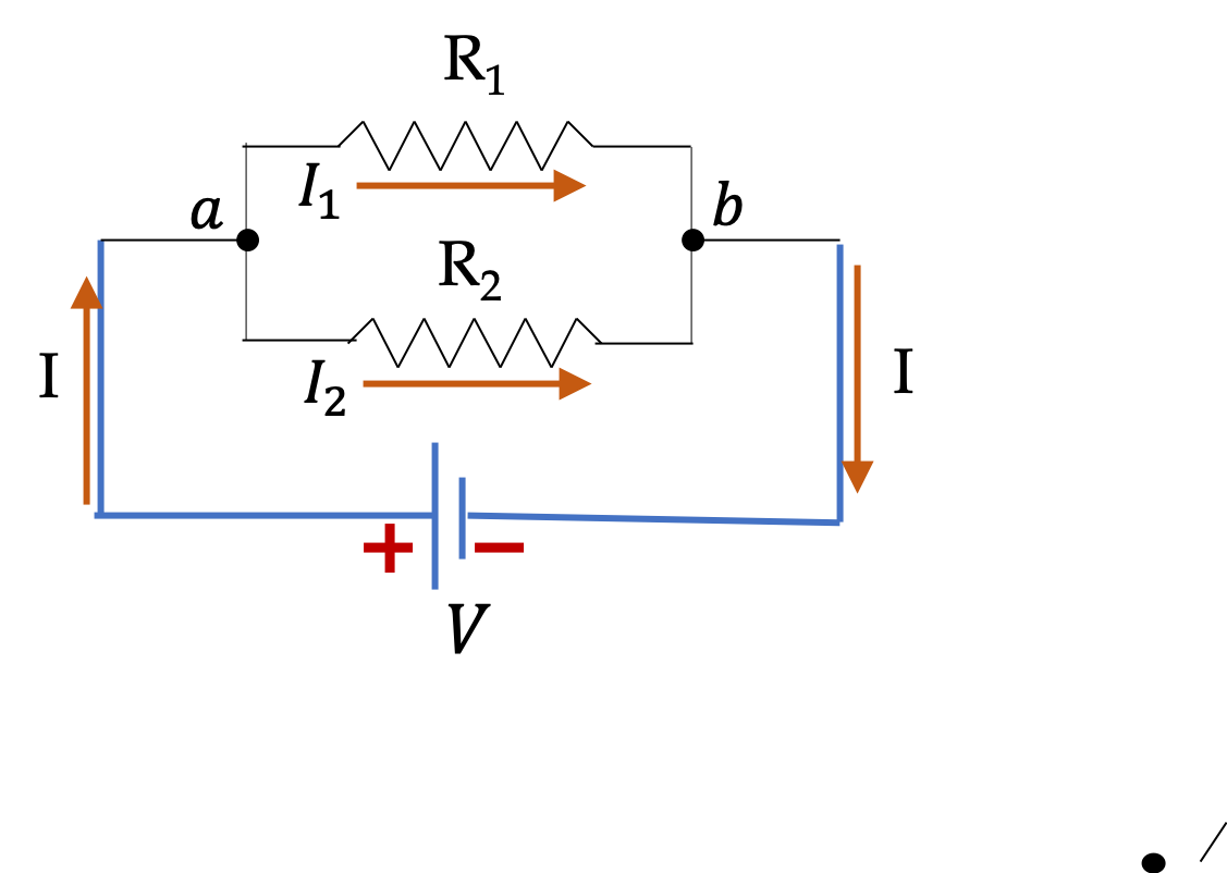
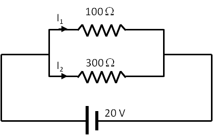
Consider the circuit given in Figure 34.38.
(a) Find percentage of current that passes through each resistor.
(b) Find equivalent resitance across the voltage source.
(c) Find current through the voltage source.
(d) Find current in each resistor.
Answer.
(a) \(75\%,\ 25\%\text{,}\) (b) \(75\ \Omega \text{,}\) (c) \(267\text{ mA}\text{,}\) (d) \(67\text{ mA},\ 200\text{ mA}\text{.}\)
Solution 1. (a)
(a) In this example, current \(I_1\) will be more than current \(I_2\) since \(I_1\) passes through the smaller resistance.
\begin{align*}
I_1 \amp = \left(\frac{300\Omega}{100\Omega + 300\Omega } \right) I = \frac{3}{4} I. \\
I_2 \amp = \left(\frac{100\Omega}{100\Omega + 300\Omega } \right) I = \frac{1}{4} I.
\end{align*}
Hence 75% of the total current passes through the \(100\;\Omega\) resistor and \(25\%\) through the \(300\; \Omega\) resistor.
Solution 2. (b)
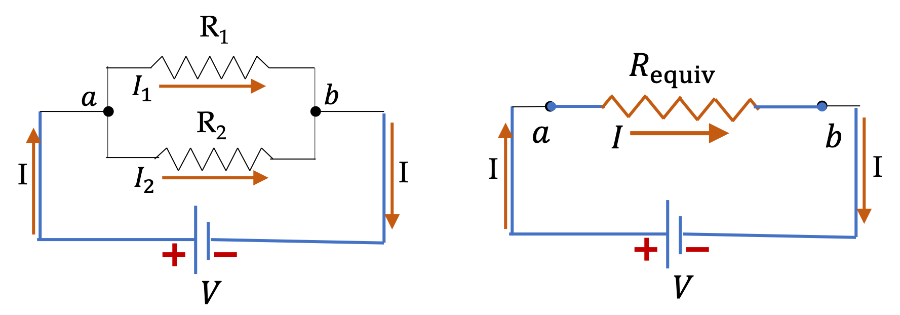
(b) The equivalent resistance across the source is the equivalent resistance of parallel resitors.
\begin{align*}
R_\text{equiv} \amp = \left( \frac{1}{R_1} + \frac{1}{R_2} \right)^{-1} = \frac{R_1 R_2}{R_1 + R_2}\\
\amp = \frac{100\Omega \times 300\Omega }{100\Omega + 300\Omega } = 75\ \Omega.
\end{align*}
Solution 3. (c)
(c) The equivalent resistance across the source is the equivalent resistance of parallel resitors.
\begin{align*}
I \amp = \frac{V}{R_\text{parallel}} = \frac{20\text{ V}}{75\ \Omega} = 267\text{ mA}
\end{align*}
Solution 4. (d)
(d) Using the results of (a) and (c) we get
\begin{align*}
I_1 \amp = \frac{3}{4} I = 67\text{ mA}.\\
I_2 \amp = \frac{1}{4} I = 200\text{ mA}.
\end{align*}