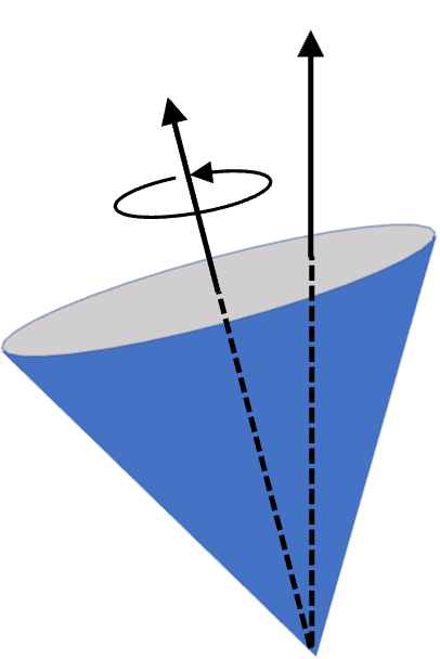
Section 10.5 The Gyroscope

Gyroscope is an important device for navigation. An important aspect of th emotion of a gyroscope is its precession about a vertical axis as illustrated in Figure 10.5.1. To understand the cause of precession we need to use vectorial nature of rotational dynamics.

Figure 10.5.1 shows a toy gyroscope. Inside a gyroscope there is flywheel which can rotate independently. The flywheel axle rotates about a fixed structure which has a rod in the direction of the flywheel's axis.

Figure 10.5.1.

Normally, you would wind a string around the axle of the flywheel. When you pull on the string while holding the outer structure, you can make the flywheel spinning at rapid pace. When spinning gyroscope is placed on a pylon, the entire structure revolves around the vertical axis.

Let \(\vec L_s\) be angular momentum of spinning of the flywheel and \(\vec L_p\) be the angular momentum of CM rotating about the verical axis.

Angular momentum of gyroscope about the pivot point O will be the sum of the two.

\begin{equation*} \vec L(t) = \vec L_s(t) + \vec L_p \end{equation*}

As a result of torque by \(mg\text{,}\) \(\vec L_s\) precesses around a vertical axis with horizontal part \(\vec L_{xy}\) of \(\vec L_s\) rotating with angular speed \(\Omega\text{.}\)

Figure 10.5.2.

The change in angular momentum \(\Delta \vec L\) will equal change in \(\Delta \vec L_s\) since \(\vec L_p\) does not change with time.

\begin{equation} \left|\Delta \vec L_s\right| = \left|\Delta \vec L\right|= \mathcal{T}_W\,\Delta t, \label{eq-delta-Ls-equal-tau-dt}\tag{10.5.1} \end{equation}

where \(\mathcal{T}_W\) is the magnitude of torque by weight. Since torque is pointed horizontally, only horizontal component of \(\vec L_s\) will change. With tilt angle \(\alpha\) with vertical, horizontal component \(\vec L_{xy}\) will be given by

\begin{equation*} \vec L_{xy} = L_s \sin\alpha \left( \cos\Omega t\, \hat i + \sin\Omega t\, \hat j \right), \end{equation*}

and the vertical component is

\begin{equation*} \vec L_z = L_s \cos\alpha\, \hat k. \end{equation*}

Since \(\vec L_s = \vec L_{xy} + \vec L_z\text{,}\)

\begin{equation*} \frac{d\vec L_s}{dt} = \frac{d\vec L_{xy}}{dt} = L_s\,\Omega\, \sin\alpha \left( -\sin\Omega t\, \hat i + \cos\Omega t\, \hat j \right). \end{equation*}

Therefore,

\begin{equation} \left|\Delta \vec L_s\right| = L_s\,\Omega\, \sin\alpha\Delta t.\label{eq-delta-Ls-equal-Omega-Ls-sin-alpha}\tag{10.5.2} \end{equation}

With gyroscope tilted at angle \(\alpha\) from vertical and CM at a distanc \(l\) from the pivot O as indicated in Figure 10.5.2, the torque will be

\begin{equation} \mathcal{T}_W = mgl\sin\alpha\text{.}\label{eq-torque-equal-mgl-sin-alpha}\tag{10.5.3} \end{equation}

Using (10.5.2) and (10.5.3) in (10.5.1), we find that angular speed of precession, called precession rate, is given by

\begin{equation*} \Omega = \frac{mgl}{L_s}. \end{equation*}

Let \(I_0\) be moment of inertia about spin axis at instant \(t\) and \(\omega\) be angular speed of spinning of th flywheel. Then, magnitude of spin angular momentum will be

\begin{equation*} L_s = I_0\omega. \end{equation*}

Therefore,

\begin{equation} \Omega = \frac{mgl}{I_0\omega}.\label{eq-precession-angular-speed-final-formula}\tag{10.5.4} \end{equation}

Thus, we find that higher the rate of spinning, i.e., larger \(\omega\text{,}\) slower the precession, i.e., smaller \(\Omega\text{.}\) An interesting aspect of this result is that precession angular speed is indepdent of the tilt angle \(\alpha\text{.}\)

Writing the moment of inertia \(I_0\) in terms of radius of gyration of the gyroscope, i.e., \(I_0 = m R_G^2\text{,}\) we see that precession angular speed is indepdent of the mass of the gyroscope.

\begin{equation} \Omega = \frac{gl}{R_G^2\omega}.\tag{10.5.5} \end{equation}

A conical shaped top with mass \(0.40\text{ kg}\text{,}\) height \(5\text{ cm}\text{,}\) and angle at tip \(45^\circ\) is spinning at \(25\text{ rev/sec}\) at angle of \(10^\circ\) with respect to the vertical. (a) What is the rate of precession? (b) What is the direction of precession when looked from above? Moment of inertia of a cone \(\frac{3}{10}MR^2\text{.}\)

Figure 10.5.4.
Hint

Spinning top is like a gyroscope.

Answer

(a) \(1.93\text{ rev/sec}\text{,}\) (b) counterclockwise sense.

Solution

(a) We notice that spinning top is just like a gyroscope. From the precession rate formula for the gyroscope, we get

\begin{equation*} \Omega = \frac{mgl}{I_0\omega}. \end{equation*}

In the present case, we have the following values

\begin{align*} m \amp = 0.40\text{ kg},\ \ g = 9.81\text{ m/s}^2,\ \ l = 2.5\text{ cm} = 0.025\text{ m}, \\ I_0 \amp = \frac{3}{10}MR^2 = \frac{3}{10}\times 0.4\text{ kg} \times (0.05\text{ m}\times \tan(22.5^\circ))^2 \\ \amp = 5.147\times 10^{-5}\text{ kg m}^2 \\ \omega \amp = 25\text{ rev/sec} = 25\times 2\pi \text{ rad/sec}. \end{align*}

We get

\begin{equation*} \Omega = 12.1\text{ rad/sec} = \frac{12.1}{2\pi}\text{ rev/sec} = 1.93\text{ rev/sec}. \end{equation*}

(b) When we look at the precessiing top from above, we will find the precession in the direction of the torque by weight. By using right hand rule on \(\vec r\times \vec F\) on frce of weight at center of mass, we get counterclockwise sense.

Subsection 10.5.1 Gyroscope as a Compass

To understand how a Gyroscope serves as a compass consider a spinning gyroscope placed on a platform that is rotated uniformly as shown in Figure 10.5.5.

Here \(\lambda\) is a fixed direction, which corresponds to latitude. In this setup, spinning disk rotates about \(PA\text{,}\) which allows change in direction of spin axis, i.e., direction of \(\vec \omega_s\text{,}\) which oscillates about direction \(\hat n\text{,}\) the axis of angular velocity \(\hat \Omega\) for rotation of the platform. In the end, \(\vec \omega_s\) aligns with \(\hat \Omega\text{.}\)

Figure 10.5.5.

The oscillation of \(\vec L_s\) can be understood by examining equation of motion for angle \(\theta\) between \(\vec \omega_s\) and \(\vec \Omega\text{.}\) A complete treatment shows that \(\theta\) will oscillate with frequency

\begin{equation*} f = \frac{1}{2\pi}\sqrt{ \frac{ I_{zz} \omega_s \Omega \cos\lambda }{I_{xx}} }. \end{equation*}

Figure 10.5.6.

For a thin disk, \(I_{xx} = \frac{1}{4}MR^2\) and \(I_{zz} = \frac{1}{2}MR^2\text{.}\) Therefore, a simpler formula is

\begin{equation} f = \frac{1}{2\pi}\sqrt{ 2 \omega_s \Omega \cos\lambda }.\label{eq-freq-gyroscope-compass}\tag{10.5.6} \end{equation}

For Earth, \(\Omega\) will be

\begin{equation*} \Omega_\text{E}=2\pi\,\text{day}^{-1} = 7.27\times 10^{-5}\,\text{sec}^{-1}. \end{equation*}

By measuring \(f\) for a set up with known spin angular speed \(\omega_s\text{,}\) we can use (10.5.6) to find \(\lambda\text{.}\)

\begin{equation*} \cos\lambda = \frac{2\pi^2 f^2}{ \omega_s \Omega_\text{E} }. \end{equation*}

Writing \(\omega_s = 2\pi f_s\) and \(\Omega_\text{E} = 2\pi f_\text{E}\text{,}\) we get a more easily usable formula.

\begin{equation*} \cos\lambda = \frac{f^2}{ 2f_s f_\text{E} }. \end{equation*}

Or, in terms of time periods, \(T\) of oscillation, \(T_s\) of spin, \(T_\text{E}\) of Earth's rotation,

\begin{equation*} \cos\lambda = \frac{T_s\, T_\text{E}}{ 2 T^2 }. \end{equation*}

For example, if oscillation time is \(30\text{ sec}\) for a gyroscope that is spinning at \(10,000\text{ Hz}\) frequency will mean latitude to be

\begin{align*} \lambda \amp = \cos^{-1}\left( \frac{ (1/10,000\text{ s})\times 24\times 3600\text{ s}}{ 2 (30\text{ s})^2 }\right)\\ \amp = \cos^{-1} (0.144) = 81.7^\circ. \end{align*}