Section 9.7 Moment of Inertia
We found above that angular momentum of a body rotating with angular velocity \(\omega \) about a principal axis is
where \(I \) is the moment of inertia of the body about the axis of rotation. If you compare this formula with the formula for the magnitude of momentum of a particle of mass \(m \) and velocity \(\vec v \text{.}\)
you will notice that moment of inertia \(I \) plays the same role in rotation as mass \(m \) plays in the translational motion.
When we studied \(\vec F = m\vec a \text{,}\) we found that mass \(m\) can be interpreted as a measure of inertia against change in velocity. Later in this chapter, when we introduce a similar dynamic equation, \(\tau = I \alpha\text{,}\) where \(\tau\) is torque of the force, we will find that \(I \) is a measure of inertia against change in angular velocity, and hence the name, moment of inertia.
In this section, we will practice computing moment of inertia of some commonly encountered objects, starting from the fundamental formula for the moment of inertia of a single particle.
Subsection 9.7.1 Moment of Inertia of Single Particle
When a single particle of mass \(m\) rotates about an axis at a distance \(R \) from the axis, it goes in a circle of radius \(R\) as shown in Figure 9.7.1. The moment of inertia of this system is the building block for more complicated systems.
Subsection 9.7.2 Moment of Inertia of Systems of Particles
Suppose we have \(N\) particles that rotate about a common axis as shown in Figure 9.7.2. The figure shows a system of 4 particles. Let \(m_1\text{,}\) \(m_2\text{,}\) \(\cdots\text{,}\) be their masses and \(R_1\text{,}\) \(R_2\text{,}\) \(\cdots\text{,}\) be their distances from the axis. The net moment of inertia will be the sum of moment of inertia for each particle.
We might write this using a sum notation.
Checkpoint 9.7.3. Moment of Inertia of a Baton about an Irregular Axis.
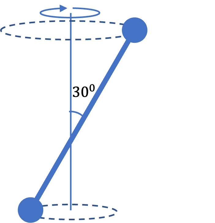
A \(1.2\text{-m}\) baton has a \(0.4\text{-kg}\) ball at each end. The rod of the baton has considerably smaller mass which we can ignore in this problem. The baton is held at \(0.5\text{ m}\) from one end and twirled so that the two masses rotate about a vertical axis at an angle of \(30^{\circ}\) from the axis.
(a) Find the distances of the two masses from the axis of rotation.
(b) Find the moment of inertia of the baton about the axis described in the problem.
(a) Draw a perpendicular from the mass to the axis - the length of that is the distance, which is the same as the radius. (b) USe point mass formula.
(a) \(0.35\text{ m}\text{,}\) \(0.25\text{ m}\) (b) \(0.074\text{ kg.m}^2 \text{.}\)
(a) 
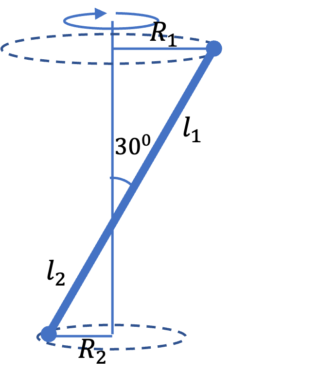
We figure out the distances from the radii of the circles in which the balls move. We do that by dropping a perpendicular from the masses to the axis and using trig on the triangle formed.
(b) From the masses and the distances from the axis, we get
Checkpoint 9.7.6. Moment of Inertia and Angular Momentum of a Three Particle System.
Three particles of masses \(m_1\text{,}\) \(m_2\text{,}\) and \(m_3\) are rotating with angular speed \(\omega\) about the given axis shown in Figure 9.7.7. Find the magnitude and direction of the total angular momentum in two different ways: (a) from a sum of the angular momentum of each particle, and (b) first finding the moment of inertia of the three as a system about the axis of rotation, and then multiplying the moment of inertia about the axis with the angular velocity about that axis.
(a) Each particle has \(l = m v r\) with \(v = \omega r\text{,}\) (b) Each particle has \(I = m r^2\) and \(l = I \omega\text{.}\)
(a) \(m_2\, \omega\, a^2\,\sin^2\theta\text{,}\) up. (b) Same as (a).
Each particle has angular momentum \(l = mvr\) where \(r\) is the radius of its circle of motion. Speed of its motion will be \(v = \omega r \text{.}\) Therefore, we will get
Using the right-hand rule, we get the direction of \(\vec l_2\) to be up. Therefore, the total angular momentum is \(m_2\, \omega\, a^2\,\sin^2\theta\text{,}\) pointed up.
The moment of inertia of a point particle is \(mr^2\) where \(r\) is the radius of its circle of motion. From the radii found in (a), we can immediately write the moment of inertia to be
Therefore, the magnitude of angular momentum will be \(I\omega\text{,}\) which is the same as we found in (a). The direction is found by applying the right-hand rule, which gives the direction up.
Checkpoint 9.7.9. Moment of Inertia and Angular Momentum of a Three Particle System Different Axis.
Three particles of masses \(m_1\text{,}\) \(m_2\text{,}\) and \(m_3\) are rotating with angular speed \(\omega\) about the given axis shown in the figure. Find the magnitude and direction of the total angular momentum in two different ways: (a) from a sum of the angular momentum of each particle, and (b) first finding the moment of inertia of the three as a system about the axis of rotation, and then multiplying the moment of inertia about the axis with the angular velocity about that axis.
(a) Find the radii of each particles circle of motion. (b) Each particle has \(I = m r^2\) and \(l = I \omega\text{.}\)
(a) \(\frac{\omega\, a^2}{\cos^2\theta}\, \left( m_1\, \sin^4\theta + m_3\,\cos^4\theta \right)\text{,}\) to the right. (b) Same as (a).
First, we figure out the radii of the circles of the motion of each particle. The figure is helpful in that.
Each particle has angular momentum \(l = mvr\) where \(r\) is the radius of its circle of motion. Speed of its motion will be \(v = \omega r \text{,}\) where \(\omega\) is same for all particles.
Therefore, we will get
Both \(l_1\) and \(l_3\) are pointed in the same direction, to the direction right. Therefore, they will add, giving us the magntitude of the net angular momentum to be
The moment of inertia of a point particle is \(mr^2\) where \(r\) is the radius of its circle of motion. From the radii found in (a), we can immediately write the moment of inertia to be
Therefore, the magnitude of angular momentum will be \(I\omega\text{,}\) which is the same as we found in (a). The direction is found by applying the right-hand rule, which gives the direction right.
Subsection 9.7.3 Moment of Inertia of a Uniform Rod
We look at the simplest continuous mass system - a rod of length \(L\) and mass \(M\text{,}\) rotating about an axis that passes through one edge perpendicular to the rod as shown in the figure.
If we divide up the rod into \(N \) parts, we can essentially turn the rod into \(N\)-particle system as shown in Figure 9.7.12.
For simplicity, let us take the segments to be of equal length \(\Delta r\text{,}\)
We now place the masses in each segment at the right end of the segments. This gives us the distance \(R_i\) to the \(i\)-th mass as follows,
with mass in each segment
This will result in the following formula for the moment of inertia.
The sum the squares of integers is known to be
Therefore, dividing up the rod in \(N\) equal parts gives us the following formula for the moment of inertia of the rod.
Cancelling \(N \) from numerator and denominator simplifies this to
Now, the original rod had many particles; in an ordinary sized rod, \(N \) would be of the order of Avogadro number, \(N_A = 6 \times 10^{23}\text{.}\) That will make adding 1 to \(N \) or to \(2N\) insignificant. Thus,
Using \(N\Delta r = L\text{,}\) the length of the rod, we finally get the formula for moment inertia of a rod about an axis through one end.
Checkpoint 9.7.13. A Chain of Rings Rotating About an Axis Through One End.
N rings, each of mass \(m\text{,}\) are linked together into a chain and hung from the middle. The chain is then rotated at an angular speed of \(\omega\) such that the angle with the vertical is \(\theta\) as shown in the figure. Model the chain as a sequence of masses separated by distance \(a \text{,}\) and find the magnitude and direction of angular momentum.
Use \(L=I\omega\text{.}\) Find \(I\) by adding up the \(I\) of each ring. You may fin dit helpful to focus on an arbitrary \(i\)-th ring.
\(\left( m a^2 \sin^2\theta\right)\, \dfrac{N(N+1)(2N+1)}{6}\, \omega\text{,}\) in direction up.
Let \(r_i\) be the radius of the circle in which the \(i\)-th ring rotates. The distance of this ring from the support is \(ia\text{.}\) Therefore, the moment of inertia of this ring is
Summing these for all \(N\) rings gives
Therefore, the magnitude of angular momentum will be
By using the right-hand rule, the direction of \(\vec L\) is up.
Subsection 9.7.4 The Parallel-Axis Theorem
The parallel-axis theorem establishes a relation between the moment of inertia about an axis through the center of mass and about another axis that is parallel to this axis. We will state it here and prove in the Calculus-based section.
Let \(M\) be the mass of the object, \(I_{\text{cm}}\) be the moment of inertia about an axis through the center of mass and \(I_{\text{A}}\) be the moment of inertia about a parallel axis that is a distance \(d\) away. Then,
Checkpoint 9.7.16. Moment of Inertia Through the CM of a Rod.
The moment of inertial of a rod of length \(L \) and mass \(M\) about an axis through one edge and perpendicular to the rod is given by
Find the moment of inertia of the rod about an axis through the center of the rod and perpendicular to the rod.
Use parallel axis theorem.
\(\dfrac{1}{12}ML^2\text{.}\)
Using the parallel axis theorem, we can write the following relation.
Using the formula, \(I_{\text{edge}} = \dfrac{1}{3}ML^2\text{,}\) given to us, we get
Subsection 9.7.5 Radius of Gyration
We ask the following question: suppose we replace a rotating body of mass \(M\) by a point particle of the same mass \(M\text{,}\) at what distance should we place this fictitious particle so that its moment of inertia will be the same as that of the original body? This distance is called the radius of gyration, which is denoted by \(R_G\text{.}\)
For instance, the moment of inertia of a disk of mass \(M\) and radius \(R\) about an axis through the center and perpendicular to the disk is
Replacing the disk by a point mass \(R_G\) away from the axis will mean
which gives
This is not the only \(R_G\) in a disk. If we rotate the disk about an axis through the center but the axis is in the plane of the face of the disk, then, we will have
giving
Thus, there is not one \(R_G \) per object, but one \(R_G\) per axis, unless the object is fully symmetric, such as a sphere. In that case there is only one \(R_G\text{,}\) which is
since moment of inertia of a sphere through any axis through its center is
Checkpoint 9.7.17. Moment of Inertia of a Disk with a Hole in the Center - Negative Mass Trick.
You cut out a circular hole of radius \(b\) from a disk of radius \(a\) and mass \(M\text{.}\) What is the moment of inertia of the resulting disk with the hole about an axis perpendicular to the disk and passing through the center? Assuming uniform density.
Think of hole as another disk with negative mass density.
\(\dfrac{1}{2} M a^2 \left( 1 - \dfrac{b^4}{a^4} \right).\)
Let \(\rho\) be the density and \(h\) the thickness.
Now, we think of the disk with the hole as a complete disk of radius \(a\) and density \(\rho\) and a second disk of radius \(b\) but of density \(-\rho\text{.}\) This way of treating hole in a material is called the negative mass trick. The moments of inertia of these two disks will be
We can write \(I_b\) in terms of \(M\) as follows
Adding the two moments we get
Checkpoint 9.7.19. Moment of Inertia of a Disk with Off-Axis Hole - Negative Mass Trick.
You cut out a circular hole of radius \(b\) from a disk of radius \(a\) and mass \(M\text{.}\) The center of the hole is at a distance \(c\) from the axis of rotation, which is perpendicular to the disk and passes through the center. What is the moment of inertia of the resulting disk about the axis through the center? Assuming uniform density.
Think of hole as another disk with negative mass density and use parallel axis theorem.
\(\dfrac{1}{2} M a^2 \left( 1 - \dfrac{b^2(b^2 + 2c^2)}{a^4} \right).\)
First we fill the hole with negative density material to get a complete disk. Thus, replacing the disk with a hole by two complete disks, one of mass \(M\) and radius \(a\) and another of mass \(-M b^2/a^2\) and radius \(b\text{,}\) but rotating with axis to center distance \(c\text{.}\)
The moment of inertia of the off-axis disk can be obtained by applying the parallel axis theorem. Thus, the moments of inertia of the two disks are
Therefore, the moment of inertial of the disk with the hole is
Subsection 9.7.6 (Calculus) Moment of Inertia of a Uniform Rod
The non-Calculus derivation of the moment of inertia of a rod about its end done above is difficult to generalize to more complicated objects, such as disk. Here, we introduce the Calculus aproach to the same problem.
We start with noting that moment of inertia will be the sum of moment onertia of all the particles of the rod. Let us look at the infinitesimal mass \(\delta m\) that is between \(r \) and \(r + dr \) from the end of the rod.
Assuming mass is distributed uniformly over the length of the rod, we can immediately write the value of \(\delta m\text{.}\)
Since this is at a distance \(r \) from the axis, its moment of inertia is
Adding the contributions of all the particles can be achieved by integrating this from \(r = 0 \) to \(r = L\text{,}\) giving the following for the moment of inertia of the rod.
Simplifying this gives us the same answer we found above.
Subsection 9.7.7 (Calculus) Proof of the Parallel Axis Theorem
Let us choose the \(z \) axis to be the orientation of the two parallel axes, one through the CM and the other through the axis A as shown in Figure 9.7.22. Let origin be at the CM, which would mean
The moment of inertia about axis through the CM will be
If axis A intersects the plane (perpendicular to the axes that contains the CM) at point P with cooridinates \((x_P, y_P, 0) \) with respect to the coordinate system with origin at the CM, then
With another coordinate system, say P\(x'y'z'\) with origin at P, we get the moment of inertial expression for \(I_{\text{A}} \text{.}\)
with
Substituting this in \(I_{\text{A}}\) we get
Therefore,
Subsection 9.7.8 (Calculus) Moment of Inertia of a Uniform Body
The method illustrated above for the moment of inertia of a rod, can be generalized for any uniform body. Let \(\delta m\) be an infinitesimal mass element whose distance from the axis is \(r \text{,}\) then its contribution to moment of inertia will be
We are using the notation \(\delta m\) for an infinitesimal mass rather than \(dm\) since we usually do not do an integral over this variable, but rather use it to think about the problem, and replace \(\delta m\) by one of the infinitesimal expressions given below, and then perform appropriate integral.
The mass \(\delta m\) will be the mass in an infinitesimal line (e.g., a bar) or an area (e.g., a thin disk) or a volume (e.g., a sphere). Depending on the situation, we will get different expressions for \(\delta m\text{.}\)
Subsection 9.7.9 (Calculus) Principal Axes and Moment of Inertia Tensor
If a body has a rotational symmetry, we can direct the Cartesian axes to take advantage of that symmetry and simplify the expressions of moment of inertia.
What happens if rotating body does not have a rotational symmetry? Turns out that every rigid body, regardless of shape, has three mutually perpendicular special directions in space, called principal axes. The moment of inertia about these principal axes are called principal moments.
Suppose we choose Cartesian axes along the principal axes, and call the moments of inertia about them to be \(I_{xx}\text{,}\) \(I_{yy}\text{,}\) and \(I_{zz}\text{.}\) Then, the angular momentum vector for any arbitrary rotation with \(\omega = (\omega_x,\ \omega_y,\ \omega_z) \) will have the following components.
In a general situation, if you are not using principal axes for your Cartesian coordinates, then, you would find that a component of the angular momentum, say \(L_x \) depends on all three components of \(\vec \omega\text{.}\)
where coefficients \(I_{xy}\) and \(I_{xz} \) of \(\omega_y \) and \(\omega_z\text{,}\) respectivley, are also moments of inertia, called the off-diagonal elements of the moment of inertia tensor. Their formulas are different than the diagonal elements. Similarly, for \(L_y\) and \(L_z\text{.}\) For a curious student, the formulas for various moments of inertia are listed here.
Checkpoint 9.7.23. (Calculus) Moment of Inertia of Rod about Axis Through the Center.
Derive the expression for the moment of inertia of a uniform rod of mass \(M\) and length \(L\) about an axis through its center and perpendicular to the rod.
Set up moment of inertial of an element at \(x\) away from axis.
\(\dfrac{1}{12}ML^2\)
Figure 9.7.24 shows the setup for the calculaton. We place the rod symmetrically on the \(x\)axis. Looking at the moment of inertia of a segment at distance \(x\) from the axis we note that the moment of inertial of \(\delta m\) in the segment will be
Integrating this from \(x=-L/2\) to \(x=L/2\) will give the answer we seek.
Checkpoint 9.7.25. (Calculus) Moment of Inertia of Triangular Plate about an Axis Through the Corner.
Derive the expression for the moment of inertia of a uniform right-angled triangle of mass \(M\text{,}\) base \(b\text{,}\) and height \(h\) about an axis through the corner of base and hypoteneus and parallel to the height side.
Place axes with origin at the corner through which axis passes and \(x\) axis along the base. Set up moment of inertia of an element at \(x\) away from axis.
\(\dfrac{1}{2} M b^2\text{.}\)
Figure 9.7.26 shows the setup for the calculaton. We place origin at the corner through which axis passes and point \(x\) axis along the base. The axis of rotation is the \(y\) axis.
Now, we look at element of width \(dx\) and height \(y\) at a distance \(x\) from the axis. Its moment of inertia is
where \(A = (1/2)bh\text{,}\) the area of the triangle. Here \(y = (h/b) x\text{.}\) Therefore, we have for the moment of inertia of the element as
Integrating from \(x=0\) to \(x=b\) will give us the answer.
We can simplify it
Checkpoint 9.7.27. (Calculus) Moment of Inertia of Right Triangular Plate About one Edge.
Derive the expression for the moment of inertia of a uniform right-angled triangle of mass \(M\text{,}\) base \(b\text{,}\) and height \(h\) about an axis coincident with the height side.
Choose \(y\) axis to be axis of rotation. Set up moment of inertia of an element at \(x\) away from axis.
\(\dfrac{1}{6}Mb^2\)
Figure 9.7.26 shows the setup for the calculaton. We place origin at the corner of right-angle. With axis of rotation to be the \(y\) axis, we have base along \(x\) axis.
Now, we look at element of width \(dx\) and height \(y\) at a distance \(x\) from the axis. Its moment of inertia is
where \(A = (1/2)bh\text{,}\) the area of the triangle. Here \(y = h - (h/b) x\text{.}\) Therefore, we have for the moment of inertia of the element as
Integrating from \(x=0\) to \(x=b\) will give us the answer.
Checkpoint 9.7.29. (Calculus) Moment of Inertia of Thin Disk about an Axis Through the Center and Perpendicular to Disk.
Derive the expression for the moment of inertia of a uniform thin disk of mass \(M\) and radius \(R\) about an axis through the center and perpendicular to the disk.
Think of a disk being made up of rings. A ring has all masses same distance from the center. Therefore, moment of inertia of ring will be \(m r^2\text{.}\) You need to think of how to add them.
\(\dfrac{1}{2}\,MR^2\text{.}\)
Figure 9.7.30 shows setup for claculations. The axis in coming-out-of page in the figure.
Now we look at an element of the disk in the shape of a ring between \(r\) and \(r+dr\text{.}\) All masses in the ring would rotated from the axis at a distance \(r\text{.}\) Therefore, moment of inertia of the ring element will beCheckpoint 9.7.31. (Calculus) Moment of Inertia of Thin Disk about an Axis Through the Center and Coplanar to Disk.
Derive the expression for the moment of inertia of a uniform thin disk of mass \(M\) and radius \(R\) about an axis through the center and coplanar to the disk, i,e., along one of its diameter.
Take \(y\) axis to be axis of rotation and an element between \(x\) anx \(x+dx\) parallel to \(y\) axis.
\(\dfrac{1}{4}\,MR^2\text{.}\)
Figure 9.7.32 shows setup for claculations. The axis is along \(y\) axis.
Now we look at an element of the disk in rectangular shape between \(x\) and \(x+dx\text{.}\) The area of the element will be \(2ydx\) since the length is \(2y\) and width \(dx\text{.}\) The \(y\) in the element area isintegrate x^2*sqrt(R^2-x^2), x
in https://www.wolframalpha.com/
and found the following answer.Checkpoint 9.7.33. (Calculus) Moment of Inertia of a Sphere about an Axis Through the Center.
Derive the expression for the moment of inertia of a uniform sphere of mass \(M\) and radius \(R\) about an axis through the center of the sphere.
With \(z\) axis as axis of rotation, consider thin disk between \(z\) and \(z+dz\text{.}\)
\(\frac{2}{5}MR^2\text{.}\)
Figure 9.7.34 shows setup for claculations. The axis of rotation is \(z\) axis in the figure.
Now we look at an element of the sphere in the shape of a disk perpendicular to \(z\) axis between \(z\) and \(z+dz\text{.}\) The radius of the disk \(r\) is
Therefore, volume of the element is
The mass of the disk is
where \(V = \frac{4}{3}\pi R^3\text{.}\) The moment of inertia of this element about \(z\) axis is
This gives
Integrating this from \(z=-R\) to \(z=R\text{,}\) which is same as \(2\times\) inegration from \(z=0\) to \(z=R\) due to evenness of the integrand, gives the answer.