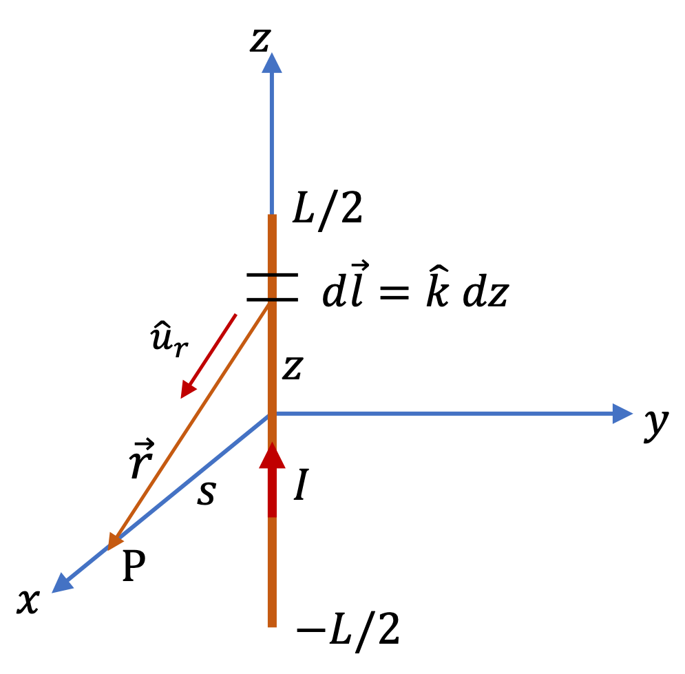
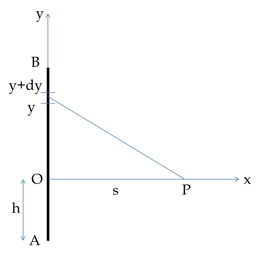
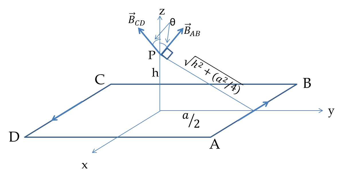
Section 39.1 Magnetic Field of Steady Current

In 1820 Hans Christian Øersted of Denmark published his finding that electric currents have magnetic effects. Here is a web link to a demo of that effect, Demo-site. There you will see a magnetic needle deflect when current passes through a metallic rod.

The discovery by Øersted inspired many other scientists, including French physicists, Jean-Baptiste Biot, Félix Savart, and André-Marie Ampère, who very quickly found the basic laws governing magnetism associated with electric currents. In this chapter we will study magnetism of steady currents.

The laws governing the magnetic field of a steady current require Calculus to state them accurately and even more Calculus to use them in prcatical situations. Here, we will state some of the more important results and defer Calculus-based discussions to subsections below.

Magnetic Field of Current in an Infinitely Long Wire

One of the most important results is that of the magnetic field from a steady current in a very long wire, say infinitely long wire. Magnetic field lines wrap around the wire in circular paths and drop off with distance from the wire. Suppose we want magnetic field a a point P which is distance \(s\) from the wire. Then, magnitude of the magnetic field is

\begin{equation} B =\mu_0\,\dfrac{I}{2\pi s},\tag{39.1.1} \end{equation}

where \(\mu_0\) is the magnetic permeability of the vacuum. It has the following exact value.

\begin{equation} \mu_0 = 4\pi\times 10^{-7} \text{ T.m/A}.\tag{39.1.2} \end{equation}

Right-hand Rule of Biot-Savart Law. We can use a right-hand rule to find the direction of magnetic field around the wire. Place your right-hand with thumb pointed in the direction of the current and sweep with your palm. The direction of the sweep is the direction of the magnetic field.

Using this right-hand rule, we find that the direction of the magnetic field is tangent to the circle at P.

In cylindrical coordinates, \(s\) is the cylindrical radial cordinate of P with wire along the \(z\) axis. Since the wire is infintely long, the field does not depend upon the \(z\) coordinate. The direction of the field depends upon the polar angle \(\phi\text{,}\) which we can use to write the direction in terms of the unit vector \(\hat u_\phi\text{.}\)

\begin{equation} \vec B =\mu_0\,\dfrac{I}{2\pi s}\,\hat u_\phi.\tag{39.1.3} \end{equation}

Magnetic Field of Current in a Coil

Another situation of great practial importance is the magnetic field of a current through a coiled wire, called solenoid, where each coil is insulated from the other coil and current in all coils are in the same direction. This physical structure is also called a solenoid.

Magnetic field of a long solenoid are shown in Figure 39.1.1. All the field lines must pass through the inside space. In a tightly-wound and very long solenoid, field is uniform inside and zero outside.

Figure 39.1.1. Magnetic field of wire flowing through coils of a solenoid.

The magnitude of the field inside is proportional to the number of turns per unit length, \(n\) and current \(I\text{,}\) and field outside zero.

\begin{equation} B = \begin{cases} \mu_0 n I, \text{ inside the solenoid.}\\ \\ 0, \text{ outside the solenoid.} \end{cases}\tag{39.1.4} \end{equation}

For direction of the field, use Biot-Savart right hand rule on current in the coil. Thus, if axis of the solenoid is the \(z\) axis, then the direction will be either towards positive \(z\) or towards negative \(z\text{.}\)

Superposition of Magnetic Field

Often, we encounter situations where more than one circuit is involved, each producing its own magnetic field. Suppose, we have two wires carrying currents with \(\vec B_1\) be the magnetic field of wire 1 and \(\vec B_2\) be the magnetic field of wire 1. The net magnetic field is just a vector sum of the two.

\begin{equation} \vec B = \vec B_1 + \vec B_2.\tag{39.1.5} \end{equation}

This is called superposition principle of magnetic field.

Suppose you are passing \(10.0\text{ amp}\) current through a \(1\text{-m}\) long wire. (a) What is the magnetic field at a point \(1\text{-cm}\) away from the wire near the half-way along the length of the wire? (b) If Earth's magnetic field at that location is \(0.5\text{ G}\text{,}\) how strong the field of the current compared to the Earth's magnetic field?

Hint

Use field for current in an infintely long wire.

Answer

(a) \(2\times 10^{-4}\text{ T}\text{,}\) (b) \(4\text{.}\)

Solution 1 (a)

(a) 
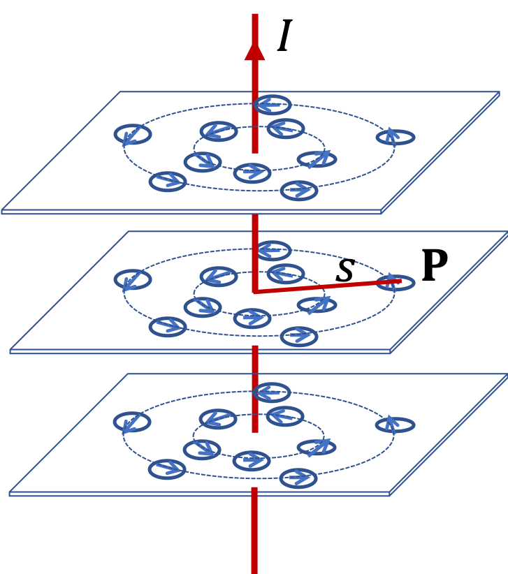
Since distance from wire is much less than the length of the wire, we can assume infinitely long wire equation applies. This gives the magnitude of the magnetic field to be

\begin{align*} B \amp = \dfrac{\mu_0}{2\pi}\,\dfrac{I}{s}\\ \amp = 2\times 10^{-7}\times\dfrac{10.0}{0.01} = 2\times 10^{-4}\text{ T} \end{align*}
Solution 2 (b)

(b) Writing the field of the current in the wire in \(\text{G}\) we have

\begin{equation*} B = 2.0\text{ G}. \end{equation*}

Therefore, the field by current is

\begin{equation*} \dfrac{B}{B_\text{earth}} = \dfrac{2.0\text{ G}}{0.5\text{ G}} = 4. \end{equation*}

That is the field of the current will be 4 times as strong.

Evaluate magnitude of the magnetic field of a \(5\text{-A}\) current in a very long straight wire at the following distance from the wire: (a) \(1\text{ cm}\) , (b) \(10\text{ cm}\text{,}\) and (c) \(100\text{ cm}\text{.}\)

Hint

Use the formula for infinetely long wire.

Answer

(a) \(10^{-4}\text{ T}\text{,}\) (b) \(10^{-5}\text{ T}\) , (c) \(10^{-6}\text{ T}\text{.}\)

Solution

Using the magnitude formula for field of current in an infinitely long wire,

\begin{equation*} B = \dfrac{\mu_0}{2\pi}\dfrac{I}{s}, \end{equation*}

we get

\begin{align*} \amp \text{(a) } B = 2\times 10^{-7}\text{T.m/A}\times \dfrac{5\text{ A}}{0.01\text{ m}} = 10^{-4}\text{ T}. \\ \amp \text{(b) } B = 10^{-5}\text{ T}. \\ \amp \text{(c) } B = 10^{-6}\text{ T}. \end{align*}

For comparision, magnetic field of Earth is \(\approx 5.0\times 10^{-5}\text{ T}\text{.}\)

Two parallel wires in a circuit are far away from other parts of a circuit that carries a \(12\text{-A}\) current as shown in Figure 39.1.5. (a) What will be magnetic field at point \(\text{P}_1\) that is \(0.4\text{ cm}\) from one wire and \(1.2\text{ cm}\) from the other wire? Give direction of the field as coming-out-of-the-page or going-in-the-page. (b) Repeat for \(\text{P}_2\text{,}\) which is \(0.4\text{ cm}\) from one wire and \(2.0\text{ cm}\) from the other wire.

Figure 39.1.5.
Hint

(a) Use right-hand rule first to get the directions so that you will know whether to add or subtract the two fields. (b) Same as (a).

Answer

(a) \(4.0\times 10^{-4}\text{ T}\text{,}\) into-the-page, (b) \(2.40\times 10^{-4}\text{ T}\text{,}\) out-of-the-page.

Solution 1 (a)

(a) Since other parts of the circuit are far away, we can ignore them and just keep the field of long wires that are nearby point P. We can also make the assumption that the formula for infintely long wire applies. Now, when we apply right hand rule, we find that field of the current in the left wire is into-the-page while the field for the current in the right wire is also into-the-page. Therefore, the two fields will add at point \(\text{P}_1\text{.}\)

\begin{align*} B_\text{into} \amp = \dfrac{\mu_0}{4\pi}\left( \dfrac{I}{s_1} + \dfrac{I}{s_2} \right)\\ \amp = 10^{-7}\times \left( \dfrac{12}{0.004} + \dfrac{12}{0.012} \right) = 4.0\times 10^{-4}\text{ T}. \end{align*}

The direction is going-into-the-page.

Solution 2 (b)

(b) Here, the direction from the nearer wire (right) is out-of-the-page and that from the farther wire (left) is into-the-page. They will oppose each other. Let's call out-of-the-page as positive and then into-the-page will be negative. Continuing to use subscript 1 for the left wire and 2 for the right wire, we get

\begin{align*} B_\text{out} \amp = \dfrac{\mu_0}{4\pi}\left( \dfrac{I}{s_2} - \dfrac{I}{s_1} \right)\\ \amp = 10^{-7}\times \left( \dfrac{12}{0.004} - \dfrac{12}{0.020} \right) = 2.40\times 10^{-4}\text{ T}. \end{align*}

Since, we found the net as positive, the out-of-page was greater. Therefore, the direction is out-of-the-page.

Subsection 39.1.1 (Calculus) Biot-Savart Law

Biot-Savart law gives us magnetic field of a steady current. By steady current we mean that charges are neither accumulating anywhere nor are they being depleted from anywhere in the circuit. The law uses superpostion of contributions from every element of the circuit to obtain the magnetic field at a point.

Biot-Savart law has a complicated mathematical form. We usually write Biot-Savart law for an infinitesimal element of the circuit. Refer to Figure 39.1.6 for the meaning of symbols. Net contribution \(d\vec B_P\) to the magnetic field at field point P a distance \(r\) away and in the direction \(\hat u_r\) from a steady current \(I\) in the infinitesimal element \(d\vec l\) is given by

\begin{equation} d\vec B_P = \dfrac{\mu_0}{4\pi}\, I\, \dfrac{d\vec l \times \hat u_r}{ r^2}.\label{eq-biot-savart-law-infintesimal}\tag{39.1.6} \end{equation}

The cross-product on the right side of this equation tells you about the right-hand rule you will need to get the direction - if you sweep from \(d\vec l\) vector in the direction of \(\hat u_r\) vector, then thumb will point in the direction of \(d\vec B_P\text{.}\) We will call this rule the Biot-Savart Right Hand Rule.

Figure 39.1.6. Set up for Biot-Savart Law for magnetic field at point P. Here, \(d\vec l\) is an infinitesimal displacement vector at source point P' in the direction of current in the wire, \(\vec r\) is displacement vector from source point P' to field point P. We also use a unit vector, \(\hat u_{r}\) in the direction from P' to P, i.e., \(\hat u_r = \vec r / r\text{.}\)

An important thing to notice in this law is that magnetic field drops off from an infinitesimal element as a square of the distance from the element. Another point is that magnetic field by a current is actually directly proportional to the current in the wire.

To obtain the field by a current in a circuit, we superimpose fields by all segments, which is done by integrating the right side of Eq. (39.1.6) over the circuit.

\begin{equation} \vec B_P = \dfrac{\mu_0}{4\pi}\, I\, \int_\text{circuit} \dfrac{d\vec l \times \hat u_r}{ r^2}.\label{eq-biot-savart-law-circuit}\tag{39.1.7} \end{equation}

All three quantities \(d\vec l\text{,}\) \(\hat u_r\text{,}\) \(r\) could potentially change as you go around the circuit. If the circuit of interest has straight segments, we can use a Cartesian coordinate to express this integral and if the circuit has circular segments, we will use a polar coordinates for them.

Equation (39.1.7) says that net magnetic field from a circuit drops off as square of distance from the circuit for sufficiently large distances. However, if a circuit extends to infinity in one direction, as in an infinite wire, the integration changes how magnetic field drops off with distance. For instance, magnetic field of an infintely long wire drops of as inverse of distance from the wire and magnetic field of a surface current is constant near the surface.

Subsection 39.1.2 (Calculus) Strategy for Setting Up Biot-Savart Problems

Biot-Savart law in Eq. Eq. (39.1.7) is written as a conceptual integral and requires setting up a coordinate system to make the integral explicit and ready for calculations. The type of coordinate system suitable for a problem depends on the geometry of the current carrying structure. We encounter two types of geometrical structures in simple applications of Biot-Savart law - straight segments and circular segments. Calculations in Biot-Savart law applications generally proceed as follows.

  1. Choose Appropriate Coordinate System.

    Choose Cartesian for straight segment. Then, your \(d\vec l\) will be

    \begin{equation*} d\vec l = \hat u_x\, dx + \hat u_y\, dy + \hat u_z\, dz \end{equation*}

    Restricting this element to the straight segment under consideration simplifies it further. For instance, if the segment is parallel to \(y\) axis, this will just be \(d\vec l = \hat u_y\, dy\text{.}\)

    Choose polar coordinate for circular segment with origin at center. Then, your \(d\vec l\) will be

    \begin{equation*} d\vec l = \hat u_\phi R d\phi, \end{equation*}

    where \(R\) is the radius of the arc where current flows. Sometimes, it helps to write \(\hat u_\phi\) using Cartesian unit vectors since \(\hat u_\phi\) has \(\phi\) dependence, which you could miss shen integrating.

    \begin{equation*} \hat u_\phi = -\hat u_x\, \sin\,\phi + \hat u_y\, \cos\,\phi, \end{equation*}
  2. Express \(\vec r\text{.}\) Suppose coordinate of element in the wire is \((x', y', z')\) and the field point P is at \((a, b, c)\text{,}\) then \(\vec r = (x'-a, y'-b, z'-c)\text{.}\) From this vector, you can obtain its magnitude as well as a unit vector in its direction. Similarly, you will work with cylindrical coordinates, if you have circular arc.
  3. Final Steps.

    Next, we work out the cross product and perform the resulting integral. Actually, doing these using Cartesian unit vectors removes a lot of mistakes I have seen students make when they try to guess their way through a calculation.

    Finally, you should verify the direction of magnetic field you got by using right-hand rule. If they differ, then there is some mistake.

One part of an electric circuit that carries a steady current \(I\) is a straight wire of length \(L\text{.}\) What is the magnetic field at a point P in the plane that divides the wire in half from the current in the straight segment only? Use symbol \(s\) for distance from the middle of the wire to the field point.

Hint

Place the wire symmetrically on the \(z\) axis and field point at \(x\) axis.

Answer

\(B\) will be ciruclating in a circular path with magnitude \(\dfrac{\mu_0 }{2\pi s}\, \dfrac{L/2}{ \sqrt{s^2 + L^2/4} }\text{.}\) The path will be counterclockwise whn viewed from approaching current direcion.

Solution

Since the wire segment is straight, we use a Cartesian coordinate system. We will place the wire symmetrically along the \(z\) axis so that the field point will be in the \(xy\) plane. We will also choose \(x\) axis direction to go through the field point P as shown in Figure 39.1.8.

Figure 39.1.8. Set up for magnetic field calculation for a finite wire. We are interested in field at a point in the plane that divides the wire equally on the two sides.

We choose an infinitesimal element between \(z\) and \(z+dz\text{.}\) This geometry gives us the following for various quantities in the infintesimal form of Biot-Savar law.

\begin{align*} \amp d\vec l = \hat u_z\, dz,\\ \amp \vec r = \hat u_x\, s - \hat u_z\, z \\ \amp r = \sqrt{s^2 + z^2 } \\ \amp \hat u_r = \dfrac{1}{\sqrt{s^2 + z^2 } } \left( \hat u_x\, s - \hat u_z\, z \right) \end{align*}

Therefore,

\begin{equation*} d\vec l \times \hat u_r = \dfrac{s}{\sqrt{s^2 + z^2 } }\, \hat j. \end{equation*}

Now, we have all the pieces to write the contribution of the steady current in the infinitesimal element at \(z\text{.}\)

\begin{equation*} d\vec B = \dfrac{\mu_0 I}{4\pi}\, \dfrac{s\, dz}{\left(s^2 + z^2\right)^{3/2} }\, \hat j. \end{equation*}

We need to integrate this from \(z=-L/2\) to \(z=L/2\text{.}\) Since integrand is an even function in \(z\) and the range of integration is symmetric around zero, we will get double the value from \(z=0\) to \(z=L/2\text{.}\)

\begin{align*} \vec B \amp = 2\times \dfrac{\mu_0 I}{4\pi}\, \int_0^{L/2}\dfrac{s\, dz}{\left(s^2 + z^2\right)^{3/2} }\, \hat j.\\ \amp = \dfrac{\mu_0 }{2\pi s}\, \dfrac{L/2}{ \sqrt{s^2 + L^2/4} }\, \hat j. \end{align*}

Picking the field point on the \(x\) axis gave us direction of the magnetic field towards positive \(y\) axis. You can show that if you pick the field point on positive \(y\) axis, you would get the direction negative \(x\) axis. The direction at arbitrary point will be in the unit vector \(\hat u_\phi\) of the cylindrical coordinate system, i.e., magnetic field in the \(xy\) plane will be circulating in circular path.

One part of an electric circuit that carries a steady current \(I\) is a straight wire of length \(L\text{.}\) What is the magnetic field at an arbitrary point P? Express your answer in terms of angles \(\theta_1\) and \(\theta_2\) subtended by the ends of the wire at the field point and distance \(s\) from the wire.

Hint

Place the wire on the \(z\) axis from \(z=0\) to \(z=L\text{,}\) and choose field point at \((x,y,z)\text{.}\) Noting that \(x\) and \(y\) appear as \(s=\sqrt{x^2 + y^2 }\text{,}\) write things in \(s\) for simplification. Rewrite the final answer in terms of angles subtended.

Answer

\(\vec B = \dfrac{\mu_0 I}{4\pi s}\, \left( \sin\,\theta_1 + \sin\,\theta_2\right)\, \hat u_\phi\)

Solution

Since the wire segment is straight, we use a Cartesian coordinate system. We will place the wire symmetrically along the \(z\) axis. We will use Cartesian coordinates \((x,y,z) \) for location of field point P as shown in Figure 39.1.10. For the segment on the wire we will use symbol \(z'\) in place of letter \(z\text{,}\) which we are using for the field point P.

Figure 39.1.10. Set up for magnetic field calculation for a finite wire. We are interested in field at an arbitrary point P.

We choose an infinitesimal element between \(z'\) and \(z'+dz'\text{.}\) This geometry gives us the following for various quantities in the infintesimal form of Biot-Savar law.

\begin{align*} \amp d\vec l = \hat u_z\, dz',\\ \amp \vec r = \hat u_x\, x + \hat u_y\, y + \hat u_z\, (z-z') \\ \amp r = \sqrt{s^2 + (z-z')^2 },\ \ s^2 = x^2 + y^2 \\ \amp \hat u_r = \dfrac{1}{\sqrt{s^2 + (z-z')^2 } } \left( \hat u_x\, x + \hat u_y\, y + \hat u_z\, (z-z') \right) \end{align*}

Therefore,

\begin{equation*} d\vec l \times \hat u_r = \left( -y\, \hat u_x + x\, \hat u_y \right) \dfrac{dz'}{\sqrt{s^2 + (z-z')^2 } }. \end{equation*}

Now, we have all the pieces to write the contribution of the steady current in the infinitesimal element at \(z\text{.}\)

\begin{equation*} d\vec B = \dfrac{\mu_0 I}{4\pi}\, \left( -y\, \hat u_x + x\, \hat u_y \right)\, \dfrac{dz'}{\left[s^2 + (z-z')^2\right]^{3/2} }. \end{equation*}

Integrating this from \(z'=0\) to \(z'=L\) gives us the following result

\begin{align*} \vec B \amp = \dfrac{\mu_0 I}{4\pi s}\, \left( -\dfrac{y}{s}\, \hat u_x + \dfrac{x}{s}\, \hat u_y \right) \left[ \dfrac{ L - z}{ \sqrt{ s^2 + (L-z)^2 }} + \dfrac{z}{\sqrt{ s^2 + z^2 }}\right]. \end{align*}

This answer can be written more compactly in terms of unit vector \(\hat u_\phi = \left( -\dfrac{y}{s}\, \hat u_x + \dfrac{x}{s}\, \hat u_y \right)\) and angles the two ends of the wire subtends at the field point P as you can see from the figure to the right.

\begin{align*} \sin\,\theta_1 \amp = \dfrac{ L - z}{ \sqrt{ s^2 + (L-z)^2 }} \\ \sin\,\theta_2 \amp = \dfrac{ z}{ \sqrt{ s^2 + (L-z)^2 }} \end{align*}

Therefore, magnetic field at P is compactly written as

\begin{equation*} \vec B = \dfrac{\mu_0 I}{4\pi s}\, \left( \sin\,\theta_1 + \sin\,\theta_2\right)\, \hat u_\phi, \end{equation*}

where \(s\) is the distance of the field point from the line of the wire. To check the direction we use the right-hand rule, which also gives the direction to be circulating as \(\hat u_\phi\) does.

A steady current \(I\) is an “infintely long” straight wire. What is the magnetic field at a point P a distance \(s\) from the middle the wire.

Hint

Take \(L/s \rightarrow \infty\) limit of answer in Checkpoint 39.1.7 or \(\theta_1 \rightarrow \pi/2\) and \(\theta_2 \rightarrow \pi/2\) limits in Checkpoint 39.1.9 .

Answer

Magnitude \(\dfrac{\mu_0 }{2\pi s}\text{.}\)

Solution

We will use answer in Checkpoint 39.1.7 and take \(L/s \rightarrow \infty\) to produce the result expected for infintely long wire. We found the magnitude of magnetic field for finite wire was.

\begin{equation*} B_P = \dfrac{\mu_0 }{2\pi s}\, \dfrac{L/2}{ \sqrt{s^2 + L^2/4} }. \end{equation*}

The limit \(L/s \rightarrow \infty\) on the right side gives

\begin{equation*} B_P = \dfrac{\mu_0 }{2\pi s} \times 1 = \dfrac{\mu_0 }{2\pi s}. \end{equation*}

The direction is given by the right hand rule. As seen in that example, magnetic fields wil go around the wire in circles.

Consider a circular loop of radius \(R\) carrying current \(I\text{.}\) Find magnetic field at a point that is a distance \(z\) above the center of the loop by (a) brute force method and (b) by exploiting symmetry in the problem.

Hint

(a) Follow the brute force process shown in previous problems. (b) Note that horizontal components canel out and you need to extract only the vertical component.

Answer

magnitude \(B_P = \frac{\mu_0I}{2} \frac{R^2}{\left( R^2 + z^2 \right)^{3/2}}.\text{.}\)

Solution 1 (a)

(a) We follow the procedures we have followed in other examples. First, we select an infintesimal element of the wire and then try to set up Biot-Savart expression for infintesimal magnetic field, which we integrate. This is not very efficient method for this problem. For more efficient method, see (b).

Let us place the ring of current in \(xy\) plane as shown in the figure. The elment is a tiny arc of length \(R\,d\phi\text{.}\) The direction of \(d\vec l\) is tangential to the circle. We write this as unit vector.

\begin{equation*} d\vec l = R\,d\phi\, \hat u_t, \end{equation*}

The unit vector in the tangent to the circle direction will be

\begin{equation*} \hat u_t = -\sin\,\phi\, \hat u_x + \cos\,\phi\, \hat j. \end{equation*}

The other vectors \(\vec r\) from infinitesimal element \((R\cos\,\phi, R\sin\,\phi, 0)\) to field point P at \((0, 0, z)\text{,}\) we need for Biot-Savart law are

\begin{align*} \amp \vec r = -R\cos\,\phi\, \hat u_x - R\sin\,\phi \,\hat u_y + z\, \hat u_z, \\ \amp r = \sqrt{R^2 + z^2}, \\ \amp \hat u_r = \dfrac{\vec r}{r} = \dfrac{-R\cos\,\phi\, \hat u_x - R\cos\,\phi \,\hat u_y + z\, \hat u_z}{ \sqrt{R^2 + z^2} }. \end{align*}

Now, we have all the parts to write the expression for \(d\vec B_P\text{.}\)

\begin{align*} d\vec B_P \amp = \dfrac{\mu_0 I}{4\pi}\, \dfrac{d\vec l \times \hat u_r}{r^2} \\ \amp = \dfrac{\mu_0 I}{4\pi\,r^2} \left( \dfrac{R h}{r}\,\cos\,\phi\,\hat u_x + \dfrac{Rh}{r}\,\sin\,\phi\,\hat u_y + \dfrac{R^2}{r}\,\hat u_z \right) d\phi \end{align*}

Integrating from \(\phi=0\) to \(\phi=2\pi\text{,}\) only the \(z\) component is nonzero.

\begin{align*} \vec B_P \amp = \dfrac{\mu_0 I}{4\pi}\dfrac{R^2}{r^3}\, 2\pi\,\hat u_z, \\ \amp = \dfrac{\mu_0 I}{2}\dfrac{R^2}{ \left(R^2 + z^2\right)^{3/2} }\, \hat u_z, \end{align*}

This gives the field at P with magnitude \(\dfrac{\mu_0 I}{2}\dfrac{R^2}{ \left(R^2 + z^2\right)^{3/2} }\) in the direction away from the ring for a point above the ring. If we had done for a point below the ring, we would have found that field is pointed towards the ring.

Solution 2 (b)

We note several simplifying features of this problem.

  1. The problem has a useful symmetry: all points of the ring are at an equal distance from the field point P.
  2. Since the direction of the current at any point of the ring is along the tangent to the circle, the angle between the current direction in any element and the direction from the element to the field point P is \(90^{\circ}\text{.}\)

Using these simplifying aspects of the problem, we find that magnetic field from each element \(dl\) of the current loop will have the same magnitude given by

\begin{equation} dB_P = \frac{\mu_0}{4\pi} \frac{I dl}{R^2 + z^2}.\label{eq-mag-filed-circular-loop-1}\tag{39.1.8} \end{equation}

However, the directions of the field at point P from current in different elements of the ring are different. Using the right-hand rule for the direction of magnetic field, we find that the directions from different parts of the ring form a cone at point P as shown in Figure 39.1.13.

Figure 39.1.13. Magnetic fields \(d\vec B_1\) and \(d\vec B_2\) by current elements at \(P_1\) and \(P_2\text{,}\) which are oppositely placed on the ring, result in the net magnetic field that has only the vertical component nonzero.

Therefore, horizontal components will cancel out and we will be left with only the vertical components of magnetic field. We seek the vertical component of a vector of magnitude dB that makes an angle \(\alpha\) with the vertical (see figure).

\begin{equation*} \left.d\vec B_P\right|_{\perp} = dB_P\ \cos\alpha, \end{equation*}

where \(\cos\alpha\) is

\begin{equation*} \cos\alpha = \frac{R}{\sqrt{R^2+z^2}}. \end{equation*}

Hence, the magnetic field at P can be written conceptually as

\begin{equation*} B_P = \int dB_P\ \cos\alpha. \end{equation*}

Substituting for \(dB_P\text{,}\) \(\cos\alpha\text{,}\) and \(dl = Rd\phi\text{,}\) we find that integration variable is the polar angle \(\phi\text{.}\) Since the integrand does not have dependence on \(\phi\text{,}\) the integration over \(\phi\) from \(0\) to \(2\pi\) give the following result for the magnitude of the magnetic field at point P.

\begin{equation} B_P = \frac{\mu_0I}{2} \frac{R^2}{\left( R^2 + z^2 \right)^{3/2}}.\label{eq-mag-field-of-current-loop-magnitude}\tag{39.1.9} \end{equation}

A wire carrying current \(I\) is bent into a square of side \(a\) as shown in Figure 39.1.15. What is the magnetic field at the center of the wire? Give direction as into-the-page or out-of-the-page.

Figure 39.1.15.
Hint

First work out directions from each segment, and then exploit th symmetry.

Answer

\(\dfrac{\mu_0 }{2\pi}\, \dfrac{L}{ s\,\sqrt{s^2 + L^2/4} }\text{,}\) out-of-the-page.

Solution

By right hand rule on each segment, we find that the fields of the four segments are all in the same direction, the direction of out-of-page. Therefore, they will all add. From symmetry, the net field will be field of one wire. The field of a single segment is for the case of a symmetric point by a finite wire as worked out in Checkpoint 39.1.7. Using the formula obtained there, the magnitude will be

\begin{align*} B \amp = 4\times \dfrac{\mu_0 }{2\pi s}\, \dfrac{L/2}{ \sqrt{s^2 + L^2/4} }\\ \amp = \dfrac{\mu_0 }{2\pi}\, \dfrac{L}{ s\,\sqrt{s^2 + L^2/4} } \end{align*}

The direction is out-page.

A very long wire is bent with a semi-circular shape at one end with radius \(R\) as shown in Figure 39.1.17. The other ends of the wires are very far away. Find the magnetic field at the center of the semicircle when a current \(I\) flows through the wire. Give the direction of the field as into-the-page or out-of-the-page.

Figure 39.1.17.
Hint

Superpose contributions from three parts. For individual parts, use formulas worked out in other exercises.

Answer

\(\frac{\mu_0I}{2R}\left( 1 + \frac{1}{\pi} \right)\text{,}\) into-the-page.

Solution

The field will be a superposition of fields from two semi-infinite wires and one half circle. The directions of all fields are into-the-page. Therefore they will all add. To get the individual fields, we appeal to the formulas worked out above in exercises. For half-circular segment we use Checkpoint 39.1.12 with height set to zero.

\begin{equation*} B_\text{circ} = \frac{\mu_0I}{2R}. \end{equation*}

To get field of semi-infinite wire, we use Checkpoint 39.1.9 with \(\theta_2=0\) and \(\theta_1=\pi/2\text{.}\) Angle \(theta_1\) is \(90^\circ\) since as the far end goes to infinity, the angle will go to this value. Since, the conttributions of the two straight parts add here, we will get

\begin{equation*} B_\text{straight} = 2\times \frac{\mu_0I}{4\pi R}. \end{equation*}

The net field will be

\begin{equation*} B = \frac{\mu_0I}{2R} + \frac{\mu_0I}{2\pi R} = \frac{\mu_0I}{2R}\left( 1 + \frac{1}{\pi} \right). \end{equation*}