Section 45.7 Optical Aberrations
Optical elements suffer from a number of problems that make the image not an exact representation of the object. These problems are not due to any faulty construction or some manufacturing defect but are inherent in the way light refracts at a spherical surface. These problems are collectively called aberrations.
Some of the aberrations in an image arise from the fact that light of different wavelength interacts differently with the material, and therefore different colored light gets separated while passing though a refracting medium. The aberrations caused by this problem are called chromatic aberrations.
Even with a quasi-monochromatic light source, i.e. a light of one color, the image would still be degraded due to the problems associated with the focusing of light for spherically curved surfaces. The problems in this category are called monochromatic aberrations or Seidel aberrations. There are five types of Seidel aberrations.
- Spherical aberration
- Coma
- Astigmatism
- Curve of field
- Distortion
Subsection 45.7.1 Spherical Aberration
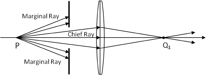
Spherical aberration results from the fact that rays from a point object on the optical axis do not focus at one image point. This is due to the fact that more oblique rays refract more strongly when they strike a spherical surface. Thus, for a convex lens the rays further away from the axis are focused closer to the lens than the rays that are near the axis as shown exaggerated in Figure 45.31.
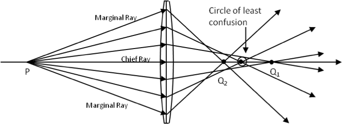
Rays that make a small angle to the optical axis are called paraxial rays and other rays are called the marginal rays. From the figure it is clear that there are several images of one point object P that fall between the image \(\text{Q}_1\) formed by the paraxial rays and the image \(\text{Q}_2\) formed by the marginal rays. The distance between the images is a measure of spherical aberration. The best image of the object is seen at a point between \(\text{Q}_1\) and \(\text{Q}_2\text{,}\) which is called the circle of least confusion.
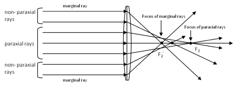
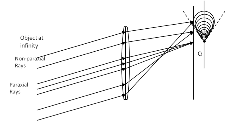
The above result for point object near the lens implies that if the object is infinitely far away, then the parallel rays from it will give rise to many foci and not one single focus as we have assumed in all our studies of a lens. For a convex lens, the marginal rays yield a smaller focal length and the paraxial rays a longer focal length ( Figure 45.32.)
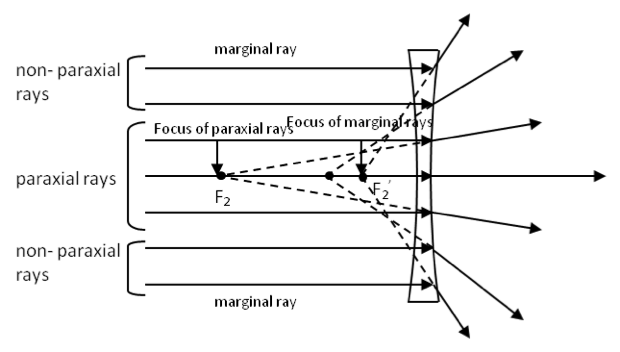
For a concave lens spherical aberration causes the marginal ray to have a longer focal length than the paraxial rays. The spherical aberration of the type displayed by the convex lens is called positive spherical aberration and the type displayed by the concave lens is called negative spherical aberration (Figure 45.33).
Clearly spherical aberration can be reduced if the rays from the object were restricted to be close to the optical axis. This is done by placing stops in front of the lens as shown in Figure 45.34.
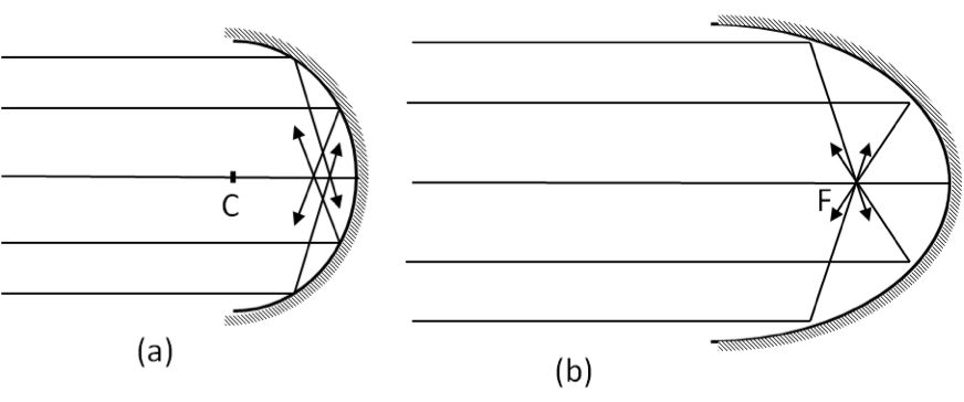
You could also ground lenses and mirror in shapes other than spherical to reduce or even eliminate spherical aberration. For instance, a parabolic mirror focuses all parallel rays to a single focal point as shown in Figure 45.35.
Subsection 45.7.2 Coma
Coma is another effect associated with non-paraxial rays, but this time for a point source located at an off-axis position (see Figure 45.36). Some of the rays from an off-axis object pass through a lens at a distance from the axis. In the image plane, the rays do not merge on a single point, but rather they are vertically distributed. The effect is called comatic aberration or coma named after the comet-like appearance of the image of a point object.
Due to coma, the non-paraxial rays may focus either away from the optical axis, or towards the optical axis. If they focus away from the axis in relation to where the paraxial rays focus, then we say that the rays are exhibiting a positive coma, and if the non-paraxial rays focus on points closer to the axis in relation to the where the paraxial rays do, then the coma is called negative coma. Coma can be reduced by limiting the non-paraxial rays, e.g., by using stops.
Subsection 45.7.3 Astigmatism
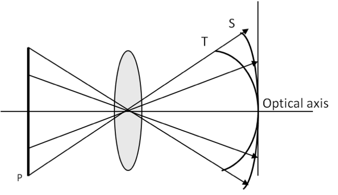
If an object is considerable distance from the optical axis, light from it will be incident on the lens with varying obliqueness depending on the direction. The more oblique rays focus nearer the lens than the less oblique rays. As a result the image is blurred. This effect is called astigmatism. To understand astigmatism in a convex lens consider an object at an off-axis point, and define a reference plane called the meridional plane consisting of the chief ray (i.e. ray from the point object that passes through the center of the lens) and the optical axis (Fig. \ref="aberration-astigmatism"}).
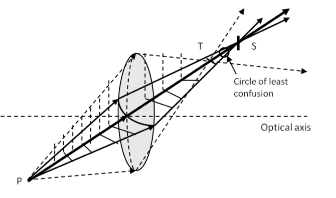
The plane perpendicular to the meridional plane is called the sagittal plane. Rays in meridional plane are more oblique than the rays in the sagittal plane causing them to refract more strongly. In the case of a convex lens, meridional rays from a point source P focus on a line T, called the primary image, which is nearer to the lens than the rays in the sagittal plane which focus on the secondary image S. The primary image T is a point in the meridional plane but a line perpendicular to the plane containing the point object P and the optical axis. The secondary image is also a line that is a point in the sagittal plane, but a line perpendicular to the primary image. In between the primary and secondary images, as you go out from the primary image line T the image expands into an ellipse and then into a circle, called the circle of least confusion, then contracts again into an ellipse and then into the secondary image line S.
For instance, points of a planar object do not focus the same distance from the lens. The focusing of an extended source is affected badly by astigmatism. For various object points P, the corresponding primary and secondary images, T and S respectively, trace out a parabolic surface whose cross-section is shown in Figure 45.38. The difference between the surfaces is a measure of astigmatism. When the T surface falls to the left of the S surface, it is called positive astigmatism, and when T falls to the right we have a negative astigmatism.
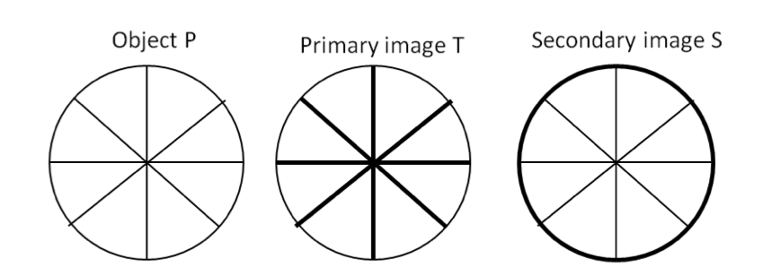
If the two surfaces coincide, then we do not have any astigmatism, and the surface is called a Petzval surface. Even when there is no astigmatism, the image of a plane object is not planar - it is curved due to the curvature of the lens. When astigmatism is absent, you do not have blurring effect mentioned above. The blurring effect due to different primary and secondary images is most strikingly seen for an object in the shape of wheel with spokes (Figure 45.39).
Astigmatism is corrected for by introducing another lens or putting a stop to prevent light from points far removed from the optical axis. Adjusting the separation between lenses also helps reduce astigmatism.
Subsection 45.7.4 Curvature of Field
In our discussion of astigmatism above, we stated that for a spherical lens primary and secondary images of a planar object forms on curved surfaces. When the primary and secondary surfaces coincide, it removes blurring of the image since all rays from a planar object now focus on the same image, and we say the image does not have astigmatism. But, even though the image is sharp, the trouble is that the image of a planar object is not planar; instead it is a curved surface. If you make a screen that matches with this curved surface, you will get a sharp image of the object, while if you try to display the image on a planar surface such as a photographic film, parts of the image will be in focus wherever the screen coincides with the Petzval surface while at other places the image will be out of focus. The effect is called curvature of field aberration. Curvature of field aberration is a big problem in slide and movie projectors where one has a flat object projected on a flat screen. Usually a combination of convex and concave lenses is employed to flatten the field and minimize the curvature.
Subsection 45.7.5 Distortion
Even when you make appropriate arrangements so that the image is sharply focused on a screen, the image may not be like the object due to different magnifications at different parts. We say the image is distorted. There are two types of distortion, pincushion distortion and barrel distortion, as illustrated in Figure 45.40.
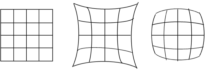
In the case of pincushion distortion, the lateral magnification increases with distance from the optical axis, while in the barrel distortion, the lateral magnification decreases with the distance from the optical axis. Distortion is inherent in spherically grounded lens and cannot be corrected by stopping marginal rays. It can be corrected only with specially ground lenses or filter optics.
Subsection 45.7.6 Chromatic Aberration
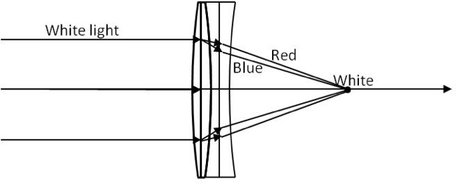
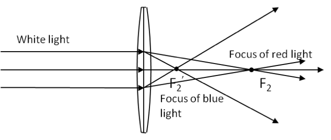
Even if you were to eliminate all five Seidel aberrations discussed above, the image made by refraction will still be different than object because the normal light is not monochromatic and each wavelength refracts differently in an optical medium. For instance, when a white light passes a lens made of glass, the red and blue lights focus at different points (Figure 45.41). This leads to colored fringes in the image, called chromatic aberration.
It is possible to completely eliminate chromatic aberration for any two wavelengths by using two lenses made up of different materials (Figure 45.42). Usually one lens is converging and the other diverging so that the separation of colors in the two lenses are in opposite directions thus canceling the effect in one lens. The combination is called an achromatic doublet or color-corrected lens. Although, the correction is exact for any two colors, the achromatic doublet usually corrects achromatic aberration for a wide range of colors. It is perhaps worth emphasizing that chromatic aberration only takes place if light passes through a medium. Thus if you make image by reflection in a curved mirror you do not have chromatic aberration.