


1. Intensity Change Due to Passing Light Through Multiple Linear Polarizers.
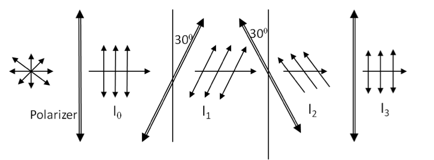
In Figure 46.20, find the intensities \(I_1\text{,}\) \(I_2\text{,}\) and \(I_3\text{,}\) in terms of \(I_0\text{.}\)
Hint.
Use Malus’s law for each polarizer.
Answer.
\(0.75\:I_0\text{,}\) \(0.19\:I_0\text{,}\) \(0.14\:I_0\text{.}\)
Solution.
We use Malus’s law for one polarizer at a time and get the intensities. The angles between the electric field direction of the incident wave and the polarizer in these cases are \(30^\circ\text{,}\) \(60^\circ\text{,}\) and \(30^\circ\text{,}\) respectively.
\begin{align*}
\amp I_1 = I_0\:\cos^2\:30^{\circ} = 0.75\:I_0,\\
\amp I_2 = I_1\:\cos^2\:60^{\circ} = \left(0.75\:I_0\right)\:\left( \frac{1}{2}\right)^2 = 0.19\:I_0,\\
\amp I_3 = I_2\:\cos^2\:30^{\circ} = 0.14\:I_0
\end{align*}


