
Section 9.8 Torque

Torque is related to the ability of a force to rotate a body about some axis. Torque is also called moment of a force.

Suppose you want to rotate a bolt by fitting a wrench on the head of the bolt and applying a force on the handle of the wrench as in Figure 9.8.1. Suppose we apply the same magnitude force at two different locations 1 and 2.

It will not surprise you that force \(\vec F_2\) on the wrench is more effective than \(\vec F_1\) in rotating the bolt. You probably know this intuitively in terms of the larger lever arm of \(\vec F_2\) compared to that of \(\vec F_1\text{.}\)

Figure 9.8.1.

In this section we will build on this intuition and define torque in precise mathematical terms. In a later section, we will use torque to quantify the change in rotation that a torque can cause - we will do that through what is sometimes called “second law of motion for rotation”.

Subsection 9.8.1 Torque of a Force that is in a Plane Perpendicular to the Axis

Consider a force on the wrench as in Figure 9.8.2. The axis is perpendicular to the page and the forces lie in the page.

Figure 9.8.2. A force on a wrench applied at P with displacement \(\vec r\) from the pivot point O. The angle between displacement of force ad force is \(\theta\text{.}\)

The axis of rotation intersects this plane at point O while the force acts at point P. We denote the displacement vector from O to P by \(\vec r \text{.}\) Then, we define the torque of force \(\vec F \) about axis through O by the cross product of vectors \(\vec r\) and \(\vec F\text{.}\)

\begin{equation} \vec{\mathcal{T}} = \vec r \times \vec F.\label{eq-torque-fundamental-definition}\tag{9.8.1} \end{equation}

Magnitude and Direction of Torque:

The definition of the cross product gives us the rules for the magnitude and the direction of the torque vector \(\vec{\mathcal{T}}\text{.}\) You will find those rules explained in the chapter on Vectors.

\begin{align} \amp \text{Magnitude, }\mathcal{T} = r\, F\, \sin\, \theta, \label{eq-torque-fundamental-definition-magnitude}\tag{9.8.2}\\ \amp \text{Direction of } \vec{\mathcal{T}}: \text{ Use Right Hand Rule of cross product}.\tag{9.8.3} \end{align}

To apply the Right Hand Rule here, hold your right hand such that the thumb points in the direction of \(\vec r \) and any of the other fingers points in the direction of \(\vec F\text{,}\) then the torque \(\vec{\mathcal{T}}\) will be perpendicular to the two vectors and will be coming out of the palm.

There are other ways of doing the right-hand rule also. For instance, if you point \(\vec r \) in the direction of \(x\) axis, and \(\vec F\) in the \(xy \) plane, then \(\vec{\mathcal{T}}\) will be in the direction of positive or negative \(z \) axis of a right-handed Cartesian coordinate system.

Components of Torque:

The definition of the cross product also gives us the rules for the components of the torque vector \(\vec{\mathcal{T}}\text{.}\) Let components of \(\vec r\) be \((x,\, y\, z)\) and that of \(\vec F\) be \((F_x,\, F_y\, F_z)\text{.}\) Then the components \((\mathcal{T}_x,\, \mathcal{T}_y\, \mathcal{T}_z)\) of \(\vec{\mathcal{T}}\) will be

\begin{align} \amp \mathcal{T}_x = y\, F_z - z\, F_y, \tag{9.8.4}\\ \amp \mathcal{T}_y = z\, F_x - x\, F_z, \tag{9.8.5}\\ \amp \mathcal{T}_z = x\, F_y - y\, F_x. \tag{9.8.6} \end{align}

If \(\vec r \) and \(\vec F \) are in the \(xy\) plane, then, this shows that torque will have only the \(z\) component non-zero.

\begin{align*} \amp \text{If }\vec r = (x,y)\text{ and }\vec F = (F_x,F_y),\\ \amp \ \ \ \text{ then } \mathcal{T}_x=0,\ \mathcal{T}_y =0, \mathcal{T}_z = x\, F_y - y\, F_x. \end{align*}

In this case, we can speak of the direction of the torque as towards positive or negative \(z \) axis, or equivalently, in the clockwise or counterclockwise sense when we look at the force from the direction of positive \(z \) axis.

Subsection 9.8.2 Zero Torque Situations

Figure 9.8.3 has four situations where torque for each force about the axis shown is zero. In (a), torque is zero because force is parallel or antiparallel to the axis. In (b), torque is zero because lever arm of each force is zero.

Figure 9.8.3.

We can take advantage of these zero torque directions to simplify calculations when we encounter a force in a completely arbitrary direction. Thus, we would first project a force on a plane perpendicular to the axis as shown in Figure 9.8.4, and work with \(\vec F_{\perp}\) component.

In our treatment in this book, if we do not explicitly acknowledge this aspect of a force, we will assume that the force is in the plane perpendicular to the axis, and \(\vec F_{\perp}\) is same as \(\vec F\text{.}\)

Figure 9.8.4. To compute the torque of a force in an arbitrary direction, we first project the force in a plane perpendicular to the axis of rotation. We require the base point P to be in this plane. Denoting the displacement vector \(\vec r \) from point O, where the axis intersects this plane, to P, we find the torque by \(\vec{\mathcal{T}} = \vec r \times \vec F_{\perp}\text{.}\)

Subsection 9.8.3 The Lever Arm Picture

The lever arm, denoted by symbol \(r_{\perp}\text{,}\) is the distance from the pivot point to the line of action of the force, where the line of action of the force stands for the infinite line that is along the force vector through the point where force acts.

Figure 9.8.5 shows the geometric construction that helps compute the lever arm. We find that lever arm \(r_{\perp}\) is

\begin{equation} r_{\perp}= r\,\sin\,\theta.\tag{9.8.7} \end{equation}

Substituting \(r_{\perp}\) for \(r\,\sin\,\theta\) in Eq. (9.8.2), we can write the magnitude of the torque vector \(\vec{\mathcal{T}}\) more simply as the product of the magnitude of the force and the lever arm.

\begin{align} \amp \text{Magnitude, }\mathcal{T} = r_{\perp}\, F. \label{eq-torque-magnitude-F-times-lever-arm}\tag{9.8.8} \end{align}

The direction of the torque is still obtained the same way as before, i.e., using the right hand rule.

Figure 9.8.5. Geometric construction for the lever arm. After indentifying the pivot point O, the force \(\vec F\text{,}\) and point P where the force acts, we extend the line along which the force acts. Then, we drop a perpendicular from O to the line of force, which is line OQ. The length of OQ is the lever arm of the force. Since \(\angle \text{OPQ} = \theta\text{,}\) the lever arm, \(r_{\perp}=\text{OQ} = r\,\sin\,\theta \text{.}\)

Subsection 9.8.4 The Sense of Rotation and Torque

Torque is nonzero if displacement \(\vec r \) and force \(\vec F \) are not parallel or antiparallel. These two vectors fall in a plane. The torque \(\vec{\mathcal{T}} \text{,}\) which is their cross product, must be perpendicular to this plane.

Let \(\vec r \) and \(\vec F \) are in the \(xy \) plane as shown in the two figures below, then, \(\vec{\mathcal{T}} \) will either be in the positive \(z\) axis direction or in the negative \(z \) axis direction.

In Figure 9.8.6 on the right, \(\vec{\mathcal{T}} \) is in the positive \(z \) axis direction. Now, when you look at the body from the positive \(z \) axis direction, i.e., from above the page, it will appear that the force is “trying” to rotate the body in the counterclockwise sense.

Figure 9.8.6.

In Figure 9.8.7 on the right, \(\vec{\mathcal{T}} \) is in the negative \(z \) axis direction. Now, when you look at the body from the positive \(z \) axis direction, i.e., from above the page, it will appear that the force is “trying” to rotate the body in the clockwise sense.

Figure 9.8.7.

Thus, we have two ways of indicating the direction of a torque: (1) towards positive or negative \(z \) axis, or, (2) counterclockwise or clockwise tendency.

Subsection 9.8.5 Net Torque

How do you add influences of two or more torques? Since torque is a vector, the sum of torques will be a vector sum.

\begin{equation} \vec{\mathcal{T}}_\text{net} = \vec{\mathcal{T}}_1 + \vec{\mathcal{T}}_2 + \cdots.\tag{9.8.9} \end{equation}

For a rotation about \(z\)-axis, we will be working with only the \(z\)-components, which will just add algebraically.

\begin{equation} \mathcal{T}_{z,\text{net}} = \mathcal{T}_{1z} + \mathcal{T}_{2z} + \cdots.\tag{9.8.10} \end{equation}

If we are thinking in terms of clockwise and countercockwise, all torques that have counterclockwise sense add together and all torques that have clockwise sense add together, and then we subtract the clockwise torque from the counterclockwise.

\begin{equation} \mathcal{T}_{\text{net}} = |\mathcal{T}_{\text{net,counterclockwise}}| - |\mathcal{T}_{\text{net,clockwise}}|.\tag{9.8.11} \end{equation}

A simple example: Suppose we have four torques, \(\vec{\mathcal{T}}_1 \) of magnitude \(12\text{ N.m}\) in the counterclockwise sense, \(\vec{\mathcal{T}}_2 \) of magnitude \(30\text{ N.m}\) in the clockwise sense, \(\vec{\mathcal{T}}_3 \) of magnitude \(25\text{ N.m}\) in the counterclockwise sense, and \(\vec{\mathcal{T}}_4 \) of magnitude \(15\text{ N.m}\) in the clockwise sense. We can add all the counterclockwise together and separately add all the clockwise together. Then, subtract the clockwise from the counterclockwise. If the result is positive, the net torque will be counterclockwise and if negative, the net torque will be clockwise. What we are doing here is summing the \(z \) components of these vectors.

\begin{equation*} \mathcal{T}_z^{\text{net}} = 12 - 30 + 25 - 15 = - 8 \text{ N.m}. \end{equation*}

Therefore, in this example, \(\vec{\mathcal{T}}_{\text{net}} \) has magnitude \(8 \text{ N.m}\text{,}\) in the negative \(z \) axis, which is also stated as clockwise sense.

A peg goes through a hole in a metal bar at one end so that the bar can rotate about the peg.

A force of \(10\text{ N}\) is applied on the bar at an angle \(30^{\circ}\) to the bar a distance \(20\text{ cm}\) from the peg as shown in the figure.

Figure 9.8.9.

(a) What is the lever arm of the force?

(b) What is the magnitude of the torque?

(c) What is the sense of rotation of the torque?

(d) If positive \(x \) axis is in the direction from peg to where force acts, and the bar and the force vector are in the \(xy\) plane, is the torque in the positive \(z \) axis direction or in the negative \(z \) axis direction?

Hint

(a) Use lever arm construction, (b) \(F\times r_{\perp} \text{,}\) (c) Use right hand rule, (d) use right hand rule.

Answer

(a) \(10\text{ cm}\text{,}\) (b) \(1.0\text{ N.m}\text{,}\) (c) Counterclockwise, (d) positive \(z \) axis.

Solution 1 (a)

(a) Let us draw the line of force and drop perpendicular to the line of force to identify the lever arm in a figure. We need to find the length of OQ. In \(\triangle \text{OPQ}\text{,}\) we have the angle \(\angle \text{OPQ} = 30^{\circ}\text{,}\) obtained from using equality of opposite angles.

Figure 9.8.10.

Therefore,

\begin{equation*} r_{\perp} = 20\text{ cm} \times \sin\, 30^{\circ} = 10\text{ cm}. \end{equation*}
Solution 2 (b)

(b) The magnitude of the torque is simply the ordinary product of the lever arm and the magnitude of the force.

\begin{equation*} \mathcal{T} = r_{\perp}\, F = 10\text{ cm}\times 10\text{ N} = 1.0\text{ N.m}. \end{equation*}
Solution 3 (c)

(c) Using the diagram, the positive \(z \) axis is out-of-page. So, we look at the diagram to get the sense of rotation. This gives the counterclockwise sense.

Solution 4 (d)

(d) The right hand rule on \(\vec r \) and \(\vec F \) gives the direction out of page, which is the direction of the positive \(z \) axis.

Several particles hit the flywheel from different directions and at different places but with the same force of \(5\times 10^{-3}\text{ N}\) as described below. In each case find the magnitude of the torque of each force on the flywheel about an axis through the center of the flywheel and perpendicular to the plane of the flywheel, i.e., about the axle at the center.

(a) Particle 1 hits the flywheel right at the center coming from the same direction as the rotation axis.

(b) Particle 2, hits the flywheel right at the center coming from the \(30^{\circ}\) to the rotation axis.

(c) Particle 3, hits the flywheel right \(0.2\text{ m} \) from the center but perpendicular to the flywheel.

(d) Particle 4, hits the flywheel right \(0.2\text{ m} \) from the center in the plane of the flywheel. But the direction of the hit passes through the center of the flywheel.

(e) Particle 5, hits the flywheel right at \(0.2\text{ m} \) from the center in the plane of the flywheel. But the direction of the hit was such that if you draw the line of the particles flight, distance to that line from the center of the wheel is \(0.15\text{ m}\text{.}\)

(f) Particle 6, hits the flywheel right at \(0.3\text{ m} \) from the center in the plane of the flywheel. But the direction of the particle's flight was such that had the particle been any further away from the center, it would have missed the flywheel.

Hint

Use definitions. Note that if force is parallel to axis, there will be no torque about that axis.

Answer

(a) \(0 \text{,}\) (b) \(0 \text{,}\) (c) \(0 \text{,}\) (d) \(0 \text{,}\) (e) \(0.75\times 10^{-3}\text{ N.m} \text{,}\) (f) \(1.5\times 10^{-3}\text{ N.m}\text{.}\)

Solution 1 (a), (b)

In both of these cases, lever arm is \(0\text{.}\) Hence Torque is zero.

Solution 2 (c)

The direction of the force is the same as the direction of the axis. Hence, torque is zero. this force cannot cause rotation around this axis.

Solution 3 (d)

The lever arm is zero. Hence torque is zero.

Solution 4 (e)

The description gives the distance from the axis to the line of force, which is what we mean by the lever arm. Thus, the lever arm is given to be \(r_{\perp} = 0.15\text{ m}\text{.}\) Therefore, the magnitude of the torque will be

\begin{equation*} \mathcal{T} = r_{\perp}\, F = 0.15\times 5\times 10^{-3} = 0.75\times 10^{-3}\text{ N.m}. \end{equation*}
Solution 5 (f)

The description gives the distance from the axis to the line of force, which is what we mean by the lever arm. Thus, the lever arm is given to be \(r_{\perp} = 0.3\text{ m}\text{.}\) Therefore, the magnitude of the torque will be

\begin{equation*} \mathcal{T} = r_{\perp}\, F = 0.3\times 5\times 10^{-3} = 1.5\times 10^{-3}\text{ N.m}. \end{equation*}

A beam of mass \(100\text{ kg}\) is supported by a cable as shown in Figure 9.8.13 with \(\theta = 30^{\circ}\text{.}\) Use \(L \) for the length of the beam - it should cancel out in the end.

(a) Find the magnitude of the tension force in the cable by setting net torque on the beam about the point where the beam is fixed to the wall to zero. (b) What will be the magnitude of the tension force if cable's angle was double, i.e., \(\theta = 60^{\circ}\text{.}\)

Figure 9.8.13.
Hint

(a) Draw lever arm diagrams for weight and tension. Also work with symbols and put numbers in the end. (b) Use general formula found in (a), (c) Use general formula found in (a).

Answer

(a) \(981\text{ N} \text{,}\) (b) \(570\text{ N}\text{.}\)

Solution 1 (a)

(a) Since we will be computing torques about the pivot point O, we disregard all forces on the beam that act at the pivot. Why? Because their lever arms will all be zero and hence their torques will be zero.

This leaves us two forces acting on the beam - (1) the weight of the beam acting at the center of mass of the beam and (2) the tension force in the cable acting at the end of the beam. Figure 9.8.14 shows these forces and the lever arm pictures of each force.

Figure 9.8.14. Figure for Checkpoint 9.8.12 solution.

Let \(L \) be the length of the beam. Then, from Figure 9.8.14(a) we immediately see that lever arm of the weight is

\begin{equation*} r_{\perp}^W = \dfrac{L}{2}, \end{equation*}

and in Figure 9.8.14(b), from the \(\triangle \text{OPQ}\text{,}\) we find the lever arm of tension is

\begin{equation*} r_{\perp}^T = L\,\sin\,\theta. \end{equation*}

Let \(M \) be the mass of the beam. Then, weight is \(W = Mg \text{.}\) This gives the following for the magnitudes of the two torques:

\begin{align*} \amp \mathcal{T}_W = Mg\dfrac{L}{2},\\ \amp \mathcal{T}_T = T L \sin\,\theta. \end{align*}

To get the net of these two torques, we need to know their directions as well. We will use the \(z \) axis notation for the direction. Let positive \(z \) axis is pointed out of page and the forces be in the \(xy\) plane. Then, by the right hand rule, we determine that

\begin{align*} \amp \text{ The torque of weight is pointed into the page, and,}\\ \amp \text{ The torque of tension is pointed out of the page.} \end{align*}

Therefore, we get the \(z \) component of the net torque to be

\begin{equation*} \mathcal{T}_z^{\text{net}} = \mathcal{T}_W - \mathcal{T}_T = Mg\dfrac{L}{2} - T L \sin\,\theta. \end{equation*}

We set this to zero and solve for \(T \text{.}\)

\begin{equation} T = \dfrac{Mg}{2\,\sin\,\theta}.\label{eq-ex-net-torque-on-a-beam}\tag{9.8.12} \end{equation}

Now, we use the numbers given to get

\begin{equation*} T = \dfrac{100\times 9.81}{2\times\sin\,30^{\circ}} = 981\text{ N}. \end{equation*}
Solution 2 (b)

(b) Since we worked with symbols in our solution, we can just use another value for \(\theta \) in Eq. (9.8.12).

\begin{equation*} T = \dfrac{100\times 9.81}{2\times\sin\,60^{\circ}} = \dfrac{981}{\sqrt{3}}= 570\text{ N}. \end{equation*}
Remark 9.8.15.

Do not confuse torque with force. They are entirely different quantities. Some major difference between torque and force to keep in mind are:

  1. Torque depends on the choice of the pivot point about which torque is to be evaluated. Force has no such dependency.
  2. Torque and force are perpendicular to each other since torque is defined as the cross product of a displacement vector and force.
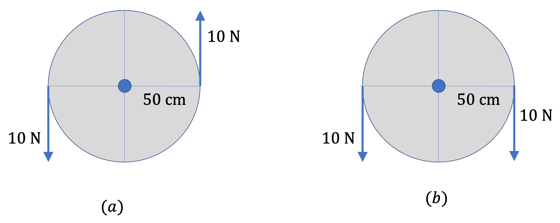
  3. There can be torque on a system even when net force is zero. For instance, in Figure 9.8.16(a), the equal magnitude forces act in the opposite directions on the opposite ends of a wheel, resulting in a zero net force, but the net torque about the center is not zero. Actually, the net torque has magnitude \(1.0 \text{ N.m}\) and direction out-of-page.
  4. Net force an a system may not be zero even when torque is zero. In Figure 9.8.16(b), the equal magnitude forces act in the same directions on the opposite ends of a wheel, resulting in a zero net torque, but non-zero net force. Actually, net force is \(20 \text{ N}\) down.
Figure 9.8.16. Net force and net torques are different things. In (a), net force is zero, but net torque is \(10 \text{ N.m}\) in the out-of-page direction. In (b) the net torque is zero, but net force is \(20 \text{ N}\) down.