Example 34.42. Circuits with Series and Parallel Connections.
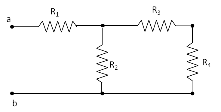
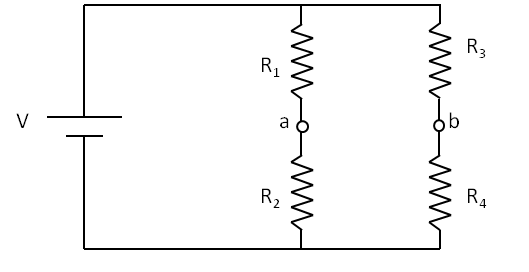
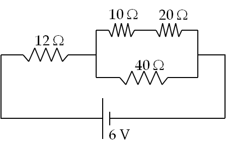
Consider four resistors connected to a voltage source as shown in Figure 34.43. Find current through each resistor.
Answer.
\(\phi_d= 0;\) \(\phi_a = 6\ \text{V};\) \(\phi_b = \frac{60}{17}\ \text{V};\) \(\phi_c = \frac{40}{17}\ \text{V}.\) \(I_1 = \frac{2}{7}\ \text{A};\) \(I_2 = \frac{3}{34}\ \text{A};\) \(I = \frac{7}{34}\ \text{A}.\)
Solution.
To find current through the resistors, we need potential drop across each. Therefore, we start with labeling the node potential points on the circuit as shown in Figure 34.44.
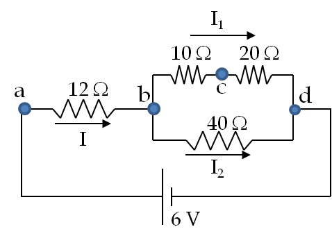
As explained above, the node points represent points of unique electric potential values. There are four nodes in the given circuit, which are labeled \(a\text{,}\) \(b\text{,}\) \(c\text{,}\) and \(d\text{.}\) Node \(d\) is connected to the negative of the source and is usually set zero volt as reference, \(\phi_d = 0\text{.}\) Since voltage of the battery is 6 volts, the potential at \(a\) is 6 V, that is, \(\phi_a = 0\text{.}\) Now, we follow step-by-step procedure of simplifying the circuit to find the potentials at \(b\) and \(c\text{,}\) viz., \(\phi_b\) and \(\phi_c\text{,}\) respectively.
Step 1:
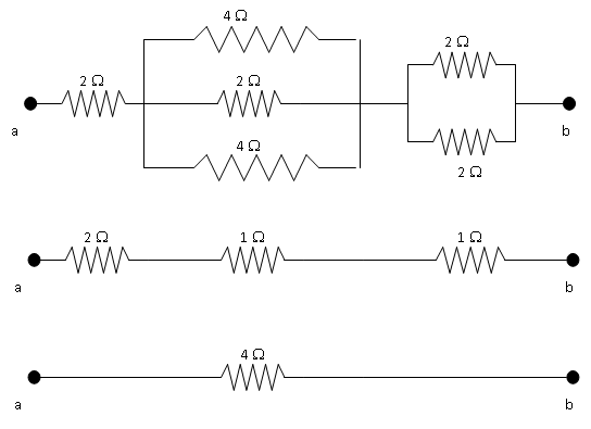
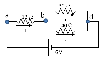
If any resistors in series, replace them by their equivalent resistors. Here only \(10\ \Omega\) and \(20\ \Omega\) are in series. Therefore, we replace them by a \(30\text{-}\Omega\) resistor as in Figure 34.45. It is best to keep the same labels here as in the previous diagram.
Step 2:
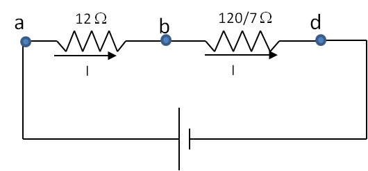
If any resistors in parallel, replace them by equivalent resistors. Here only 30 \(\Omega\) and 40 \(\Omega\) are in parallel. Therefore, we replace the combination by their equivalent resistance, which is \(\frac{120}{7}\ \Omega\) as in Figure 34.46
Step 3:
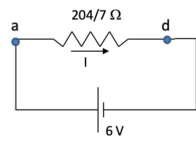
After replacing the parallel resistors by \(\frac{120}{7}\ \Omega\text{,}\) we find that it is in series with the \(12\text{-}\Omega\) resistor. Therefore current through the \(\frac{120}{7}\ \Omega\) must be same as that goes through the \(12\text{-}\Omega\) resistor. Now the two resistors in series can be replaced by a \(\frac{204}{7}\text{-}\Omega\) resistor resulting in a really simple circuit. The current through the \(\frac{204}{7}\text{-}\Omega\) resistor must be same as the \(12\text{-}\Omega\) or \(\frac{120}{7}\text{-} \Omega\) resistor since it is replacing resistors in series (Figure 34.47).
Step 4:
Now, we can use Ohm’s law to find the current through \(\frac{204}{7}\text{-}\Omega\) resistor.
\begin{equation*}
I = \frac{6V}{(204/7)\Omega} = \frac{7}{34}\ \text{A}.
\end{equation*}
Step 5:
We then trace our path backwards towards the original circuit. The current through the \(12\text{-}\Omega\) resistor is also \(7/34\text{ A}\text{.}\) Therefore, potential drop across the \(12\text{-}\Omega\) resistor is
\begin{equation*}
\phi_a-\phi_b = \frac{7}{34}\ \text{A} \times 12\ \Omega = \frac{42}{17}\ \text{V}.
\end{equation*}
The potential drop across the \(\frac{120}{7}\text{-} \Omega\) resistor is \((60/17)\text{V}\text{.}\)
\begin{equation*}
\phi_b-\phi_d = \frac{7}{34}\ \text{A} \times \frac{120}{7}\ \Omega = \frac{60}{17}\ \text{V}\ \ \Longrightarrow\ \phi_b = \frac{60}{17}\ \text{V}.
\end{equation*}
Going back one more step we find that potential drop across the \(30\text{-}\Omega\) resitor is same as that across the \(\frac{120}{7}\text{-}\Omega\) resistor we worked out. Hence, current through the \(30\text{-}\Omega\) resistor is simply
\begin{equation*}
I_1 = \frac{(60/17)\ \text{V}}{30\ \Omega} = \frac{2}{17}\ \text{A}
\end{equation*}
Therefore, voltage \(\phi_c\) is obtained from the potential drop across the \(20\text{-} \Omega\) resistor as given by
\begin{equation*}
\phi_c - \phi_d = \left( \frac{2}{17}\ \text{A} \right) \times 20\ \Omega = \frac{40}{17}\ \text{V}.
\end{equation*}
Since \(\phi_d = 0\text{,}\) we obtain \(\phi_c = \frac{40}{17}\ \text{V}\text{.}\) We can use the node voltages to obtain the current through various resistors. Alternately, since the total current \(I\) was split into \(I_1\) and \(I_2\text{,}\) we can find \(I_2\) by subtracting \(I_1\) from \(I\text{.}\)
\begin{equation*}
I_2 = I - I_1 = \frac{7}{34}\ \text{A} - \frac{2}{17}\ \text{A} = \frac{3}{34}\ \text{A}
\end{equation*}
Summarizing the answer:
\begin{align*}
\amp \phi_d= 0;\ \phi_a = 6\ \text{V};\ \phi_b = \frac{60}{17}\ \text{V};\ \phi_c = \frac{40}{17}\ \text{V}.\\
\amp I_1 = \frac{2}{7}\ \text{A};\ I_2 = \frac{3}{34}\ \text{A};\ I = \frac{7}{34}\ \text{A}.
\end{align*}