
Section 38.9 Torque on Current Carrying Wire

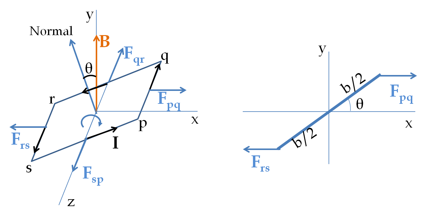
Consider a rectangular loop of current in a uniform magnetic field as shown in Figure 38.9.1. For future use, I have chosen normal direction by using a right-hand rule to sweep around the loop in the direction of the current and thumb giving the direction of normal. We will examine the torque at an instant when the normal to the loop makes an angle \(\theta\) with respect to the magnetic field. Let the loop be pivoted about an axis perpendicular to the magnetic field and passing through the middle of two of the sides of the loop as shown in the figure.

Figure 38.9.1. Torque on a rectangular current loop. The side pq is of length \(a\) while side qr is of length \(b\text{.}\) Current \(I\) flows in the wire and the uniform magnetic field \(B\) is pointed towards positive \(y\) axis. The axis of rotation is pointed along the \(z\) axis. The magnetic force acts on the conduction electrons. The figure on right shows forces in the \(xy\)-plane as seen from the positive \(z\) axis.

The mangentic forces on segments qr and ps are parallel to the \(z\) axis and will not have any torque about the \(z\) axis. Therefore, we only need torques by forces \(\vec F_{pq}\) and \(\vec F_{rs}\) on pq and rs respectively. The magnitudes of these toques about the \(z\) axis are equal and have the same sense of rotation, which can be seen to be clockwise sense in right side of Figure 38.9.1.

Therefore, it is sufficient to figure out torque by \(\vec F_{pq}\) only and multiply the result by 2. Using the magnetic force on the current in the pq segment we find the force to be

\begin{equation*} \vec F_{pq} = -I a \hat k \times B \hat j = Ia B \hat i, \end{equation*}

where \(a\) is the length of the pq segment and I used the unit vectors along the Cartesian axes. To get a better feel of the direction of the forces, right side of Figure 38.9.1 shows the forces in the \(xy\)-plane. The lever arm of this force is

\begin{equation*} l_\perp = \dfrac{b}{2}\,\sin\,\theta. \end{equation*}

Therefore, the torque has magnitude

\begin{equation*} \tau_{pq} = I a B \dfrac{b}{2}\,\sin\,\theta, \end{equation*}

with clockwise sense of rotation. Multiplying this by 2 we get the net torque to be

\begin{equation*} \tau_\text{net} = I a b B \sin\,\theta \end{equation*}

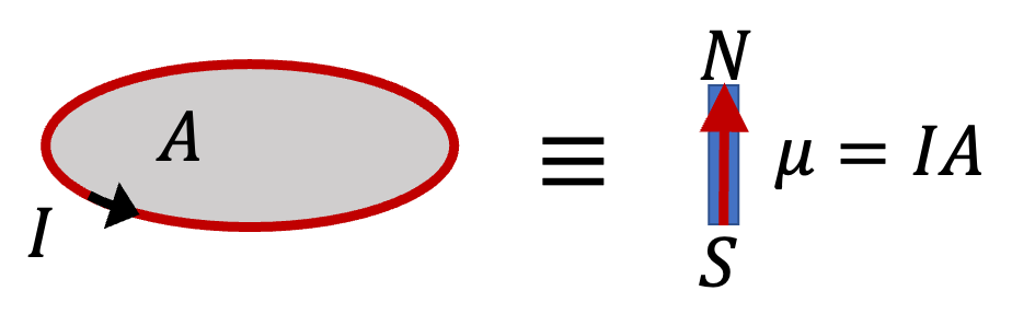
Notice that \(a\times b\) is area \(A\) of the loop. Therefore, we can write this result in another form.

\begin{equation} \tau_\text{net} = I A B \sin\,\theta\label{eq-torque-on-one-rectangular-loop}\tag{38.9.1} \end{equation}
Remark 38.9.2. Torque on \(N\) Loops.

If you had many loops all carrying current in the same orientation, theo torques on all of them will add up. Thus, for a coil of \(N\) loops, you will get \(N\) times the torque.

\begin{equation} \tau_\text{net}^{N\text{-loops}} = N \tau_\text{net}^{\text{one-loop}} = N I a b B \sin\,\theta.\tag{38.9.2} \end{equation}

This is the strategy behind using coils in motors for increasing the torque provoded by the motor.

Subsection 38.9.1 Magnetic Dipole Moment of Current Loop

Formula (38.9.1) is same as the formula for torque on a magnetic dipole given in (38.5.1) if we identify the product of current and area as the magnetic dipole moment. Let us denote this dipole moment by \(\mu_\text{dip}\text{.}\)

\begin{equation} \mu_\text{dip} = I A.\tag{38.9.3} \end{equation}

This means that every current loop with the same product \(IA\) will have the same same torque on it. Not only that, we can also define magnetic dipole moment vector by treating loop area as a vector, \(\vec A\text{.}\) The loop vector area \(\vec A\) has magnitude equal to the area \(A\) and direction in the direction of normal to the loop using right-hand rule on the current.

Although, we obtained result in (38.9.1) by examining a rectangular loop, one can prove that this result applies to all flat loops, i.e., loops that can be placed in one plane. That is, shape of the loop does not affect our result.

Subsection 38.9.2 Modeling Magnetic Dipoles as Current Loops

In Section 38.5 when we studied forces and torques on magnetic dipoles, we thought of magnetic dipoles as tiny magnets with north and south poles. The analogy between the behavior of loops of current and magnetic dipoles in an external magnetic field can be used to get another model for tiny magnets, and magnetic dipoles, in general.

In this picture, we think of a physical magnetic dipole as a tiny loop of current with some area \(A\) and some current \(I\) so that their product \(IA\) is equal to the magnetic dipole moment \(\mu\) of the physical dipole.

Figure 38.9.3. Two ways to look at a tiny magnet.

Of course, there are infinitely many possibilities for \(A\) and \(I\) that will give the same product \(IA \text{.}\) Any small area loop and the corresponding current can be used to “represent” a physical dipole. In the infintesimal limit of area, the model represents the actual physical microscopic dipole.