Section 44.7 Circuit Analysis Using Complex Numbers
The equations resulting from the application of Faraday's loop rule to an AC circuit results in the summation of sine and cosine functions. These calculations using the trigonometric functions are usually messy and an alternative method is desirable. It turns out that the algebra of complex numbers is better at these calculations than the sine and cosine functions.
The connection between complex analysis and sines and cosines comes from Euler's formula
where \(i = \sqrt{-1}\text{.}\) Here, \(\cos\,\theta\) is the real part of \(e^{i\theta}\) and \(\sin\,\theta\) is the imaginary part of \(e^{i\theta}\text{.}\) Thus, in AC circuit calculations, we replace the cosine of the source voltage by a complex exponential. Then, we perform regular algebra. After completing the calculations, the real part of the final result corresponds to the answer we seek.
To distinguish complex voltage representing a real voltage, we will use the same symbol, but place a tilde (~) sign above the symbol, and similarly for currents. Thus, we will replace
by
whose real part is the original real voltage. As a result, the complex voltage \(\tilde{V}\) across an element and complex current \(\tilde{I}\) through it, are related by a complex version of Ohm's law, we can call Complex Ohm's Law.
where the complex “resistance” denoted by \(\tilde{Z}\) is called the impedance or the complex impedance of the element. In the following we will work out expressions for complex impedances of resistor, inductor and capacitor. We will find that complex impedance of inductor and capacitor are imaginary with absolute values equal to their reactances.
The inverse of the impedance is called admittance and is denoted by \(\tilde{Y}\text{.}\)
We will see that the complex impedance allows one to treat resistors, capacitors and inductors in an AC circuit on an equal footing.
Subsection 44.7.1 Rectangular and Polar Forms of Complex Numbers
You may already know that a complex number has two parts and can be written using \(i=\sqrt{-1}\text{.}\) For instance, \(3+i4\) is a complex part whose real part is \(3\) and imaginary part \(4\text{.}\) This is called complex number written in rectangular or Cartesian form. You can imagine this as point \((3,4)\) in a complex plane. You can think of complex plane as Cartesina \(xy\)-plane.
Just as you can represent a point in \(xy\)-pane by \((x,y)\) coordinates or corresponding polar coordinates \((r,\theta)\text{,}\) you can do the same with a complex number. Thus, number \(3+i4\) will have polar representation \(re^{i\theta}\) with
We call \(r\) absolute value or amplitude of the complex number \(x+iy\) and \(\theta\) phase of the complex number. Suppose, we denote complex number \(x+iy\) by letter \(z\text{.}\) Then, we will often write its \(r\) as \(r = |z|.\) For instance, absolute value of complex impedance is equal to the amplitude of the impedance we have defined above.
Also, note that absolute value of a complex number with \(r=1\) will be 1. That is, if a complex number is purely exponential, i.e, if \(z=e^{i\theta}\text{,}\) then
Yoou can immediately verify this by using Euler's formula given above and \(\cos^2\theta + \sin^2\theta = 1\text{.}\)
Subsection 44.7.2 Complex Impedance of a Resistor
Since current \(I(t)\) through a resistor and \(V_R(t)\text{,}\) the voltage drop across a resistor are in-phase, when we take their ratio to get impedance, the exponetials will cancel out, leaving just the real resistance \(R\text{.}\)
Subsection 44.7.3 Complex Impedance of an Inductor
Since current \(V_L(t)\) across an inductor leads current \(I(t)\) through it by a phase of \(\pi/2\) radians, their ratio will give reactance times an exponential with a positive phase constant.
where I used \(e^{i \pi/2} = \cos\, \pi/2 + i\, \sin\, \pi/2 = 0 + i = i\text{.}\) Note that absolute value of this impedance is the expected reactance of the inductor.
The phase of complex \(Z_L\) is \(\frac{\pi}{2}\text{.}\)
Subsection 44.7.4 Complex Impedance of a Capacitor
Since current \(V_L(t)\) across a capacitor lags current \(I(t)\) through it by a phase of \(\pi/2\) radians, their ratio will give reactance times an exponential with a negative phase constant.
where I used \(e^{i \pi/2} = \cos\, \pi/2 - i\, \sin\, \pi/2 = 0 - i = - i\text{.}\) Note that absolute value of this impedance is the expected reactance of the capacitor.
The phase of complex \(Z_C\) is \(-\frac{\pi}{2}\text{.}\)
Subsection 44.7.5 AC Circuit Problems
The first step in the analysis of an AC circuit is to replace circuit elements by their impedances. Each resistor \(R\) is replaced by its \(Z_R = R\text{,}\) each inductance \(L\) is replaced by its impedance \(Z_L = i\omega L\text{,}\) and each capacitance is replaced by its impedance \(Z_C =1/ i\omega C\text{.}\) Then, we subject the circuit by Kirchoff's current law for complexe currents and Faraday's loop rule for each loop in the circuit. We then, solve for complex currents and deduce the physical currents from the real parts of the complex currents. These steps are best illustrated by examples.
Example 44.7.1. Series RLC Circuit in Complex Notation.
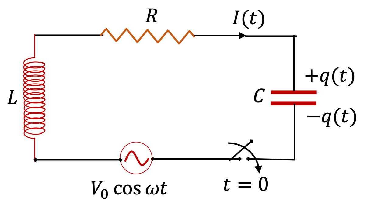
Consider the series RLC-circuit. Find current in the circuit.

Replace passive circuit elements by their complex impedances and treat them as resistors.
\(I_0 = \dfrac{V_0}{ \sqrt{ R^2 + \left( \omega L- \dfrac{1}{\omega C}\right)^2 } }\text{,}\) \(\phi_I = - \tan^{-1} \left( \dfrac{\omega L- \dfrac{1}{\omega C}}{R} \right)\text{.}\)
First step in our solution is to replace original circuit by a complex circuit where we replace \(R\) by \(Z_R\text{,}\) \(C\) by \(Z_C\text{,}\) and \(L\) by \(Z_L\text{,}\) and treat currents and voltages complex. This is shown as a complex circuit in the figure below.

Now, we think of impedances as if they were simple resistors. In this circuit, the loop equation will give
which can be solved for complex current.
From this we note that complex impedance of the circuit is
This is rectangular form of complex impedance, which we can also write in polar form. Let
Then,
Using polar form of complex impedance in Eq. (44.7.3) we get polar form of complex current.
whose real part gives the physical current in the circuit.
Wrting this as \(I(t) = I_0\,\cos(\omega t + \phi_I)\) we have
Example 44.7.4. Parallel RL Circuit in Complex Notation.
Consider the circuit given in the Fig. \ref{fig:example-ac-RL-1} where a resistor \(R\) and an inductor \(L\) are connected in parallel to an AC power generator with voltage \(V(t) = V_0\cos(\omega t)\text{.}\) Find (a) current in each branch of the circuit, (b) average power dissipated in the resistor, and (c) average power produced by the AC generator.

Replace passive circuit elements by their complex impedances and treat them as resistors.
(a) \(I_1(t) = \dfrac{V_0}{R}\,\cos(\omega t)\text{,}\) \(I_2(t) = \dfrac{V_0}{\omega L}\,\sin(\omega t)\text{,}\) \(I = I_1 + I_2\text{,}\) (b) and (c) \(\dfrac{1}{2}\,\dfrac{V_0^2}{R}\)
(a) First step in our solution is to replace original circuit by a complex circuit where we replace \(R\) by \(Z_R\text{,}\) and \(L\) by \(Z_L\text{,}\) and treat currents and voltages complex. This is shown as a complex circuit in the figure below.

From loop with source and \(\tilde Z_R\) we get
whose real part gives the physical current through \(R\text{.}\)
From loop with source and \(\tilde Z_L\) we get
whose real part gives the physical current through \(L\text{.}\) To obtain the real part of this complex quantity we note that
which can be combined with \(e^{i\omega t}\) to give
whose real part is
which we can also write as
Conservation of current at nodes gives the overall current.
We can write this answer as \(I_0\,\cos(\omega t + \phi_I)\) with the following answer.
To see these expressions, you can either expand \(I_0\,\cos(\omega t + \phi_I)\text{,}\) equate the result to the answer in Eq. (44.7.4), separately equate coefficients of \(\cos(\omega t)\) and \(\sin(\omega t)\text{,}\) and then solve for the phase constant and amplitude.
(b) The instantaneous power dissipated in the resistor will be
Average of \(\cos^2(\omega t)\) is \(\dfrac{1}{2}\text{.}\) Therefore, average power dissipates is
(c) The instantaneous power delivered to the circuit by the source will be
Average of \(\cos(\omega t) \cos(\omega t + \phi_I)\) is \(\dfrac{1}{2}\cos\,\phi_I\text{.}\) Therefore, average power dissipates is
This is the same as the energy dissipated in the resistor, the only place where energy could have gone.
Example 44.7.7. Circuit Elements in Series and in Parallel.
(a) Find current through the capacitor in the circuit. (b) Use the following values to find the numerical values of the magnitude and phase of the current through the capacior.

Replace passive circuit elements by their complex impedances and treat them as resistors.
(a) See solution, (b) \(64\; \text{mA}\text{,}\) \(\pi/2\)
(a) We start by first replacing the passive elements in the circuit by their impedances.

Since we just want the current through \(C\text{,}\) which is the same as current through the source, we will work out equivalent impedance of everything connected across the source. We see that \(\tilde{Z}_C\) is in series with parallel combinations of \(\tilde{Z}_R\) and \(\tilde{Z}_L\text{,}\) the equivalent impedance is
This gives real and imaginary parts of the equivalent complex impedance.
Therefore, we have \(Z = |Z|e^{i\phi_Z}\) with
Using the magnitude and phase of equivalent impedance, we can immediately write the magnitude and phase of current through the course, \(I = I_0\cos(\omega t + \phi_I)\text{,}\) with
(b) The value of impedances of the elements are:
The equivalent impedance becomes
The amplitudes and phase of the current would be,