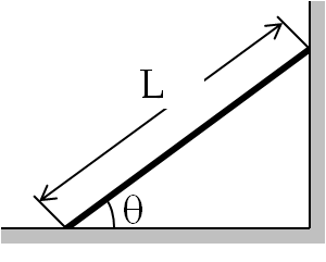
Example 16.1. Angle for a Board to Rest Against a Wall.
A board of mass $m$ and length $L$ is resting against a vertical wall. The coefficient of static friction between the board and the wall and between the board and the floor are $\mu_w$ and $\mu_f$ , respectively. Find the minimum angle $\theta$ the board may be placed without slipping.
Solution.
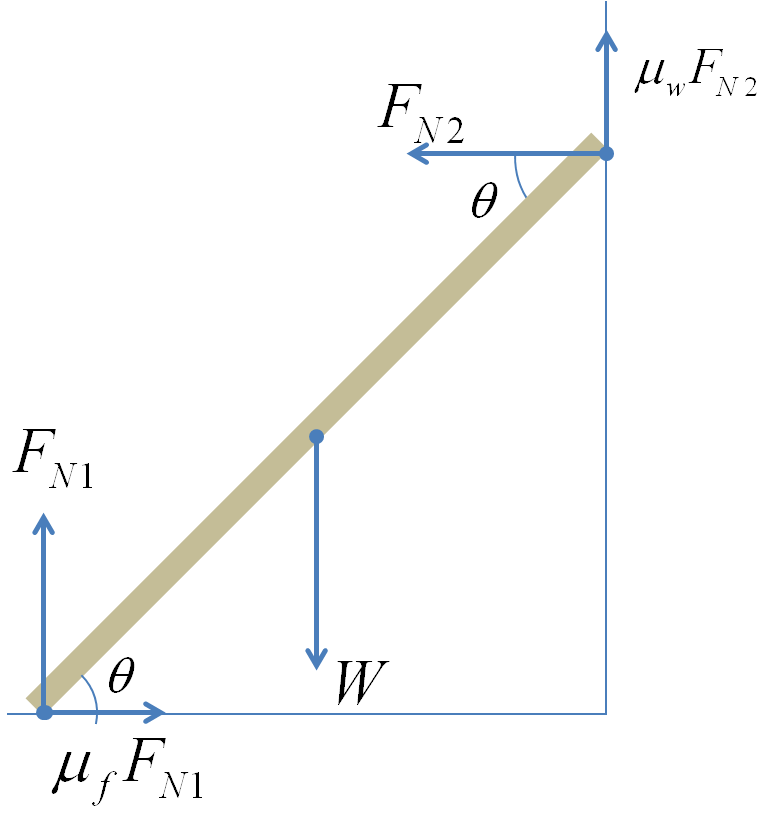
First we identify forces on the board. The forces on the borad are its weight at the center of gravity of the board, the normal forces $F_{N1}$ and $F_{N2}$ from the floor and the wall respectively, and the maximum static frictions from the floor and the wall as shown in the figure.
The balancing of forces gives
\begin{align}
\amp \mu_f F_{N1} -F_{N2} = 0.\tag{16.13}\\
\amp F_{N1} + \mu_w F_{N2} -W = 0. \tag{16.14}
\end{align}
The balancing of the torque about the point where the board touches the wall gives
\begin{equation}
\frac{1}{2}L W \cos\theta-L F_{N1}\cos\theta + L \mu_f F_{N1} \sin\theta = 0,\tag{16.15}
\end{equation}
where I have used + for the torques pointed out-of-page and - for the torque pointed into-the-page.
From Eq. (16.13) we get $F_{N2}$ in terms of $F_{N1}$.
\begin{equation*}
F_{N2} = \mu_f F_{N1},
\end{equation*}
which we use in Eq. (16.14) to find
\begin{equation*}
F_{N1} = \frac{W}{1+ \mu_w \mu_f},
\end{equation*}
which can be used in Eq. (16.14) to arrive at
\begin{equation*}
\tan\theta = \frac{\frac{1}{2} + \mu_w\mu_f}{\left(1+ \mu_w \mu_f \right)\mu_f}.
\end{equation*}


