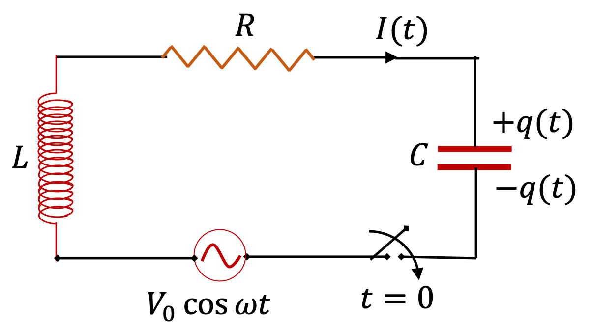
Section 44.5 RLC Circuits

Figure 44.5.1 shows a circuit that has all three basic circuit elements, namely a resistor \(R\text{,}\) an inductor \(L\) and a capacitor \(C\) connected in series with an alternating EMF source with voltage \(V(t) = V_0\:\cos(\omega t)\text{.}\)

Figure 44.5.1. A series RLC-circuit driven by an alternating EMF.

We have already studied this circuit in the last chapter. The analysis starts by writing down the Faraday loop rule, which is same as Kirchoof's KVL in this case. We get the following integro-differential equation for the current at instant \(t\text{.}\)

\begin{equation} L\frac{dI}{dt} + R I + \frac{1}{C}\int^t I(t')dt' = V_0\cos(\omega t).\tag{44.5.1} \end{equation}

Taking a derivative of \(t\) converts this to a second order differential eqaution.

\begin{equation} L\frac{d^2 I}{dt^2} + R \frac{dI}{dt} + \frac{1}{C}\;I = -\omega V_0\sin(\omega t).\label{eq-equation-of-motion-RLC}\tag{44.5.2} \end{equation}

In AC circuit analysis, we are interested in only the steady state solution, which we recall now. In steady state, current oscillates with the same frequency \(\omega\text{,}\) but its phase constant may be different than the phase constant of the source emf. Therefore, we seek solution of the form

\begin{equation} I(t) = I_0\:\cos(\omega t + \phi_I).\tag{44.5.3} \end{equation}

We find \(I_0\) and \(\phi_I\) that solves Eq. (44.5.2) by inserting \(I(t)\) in that equation, expanding the trig functions, collecting terms that multiply \(\sin(\omega t)\) and \(\cos(\omega t)\text{.}\) We then equate the multipliers of \(\sin(\omega t)\) and \(\cos(\omega t)\) from both sides. These steps are left as an exercise for the student. In the end, you will find the following answer.

\begin{align} \amp I_0 = \dfrac{V_0}{\sqrt{R^2 + \left(\omega L - \dfrac{1}{\omega C} \right)^2}},\label{eq-RLC-driven-current-amplitude}\tag{44.5.4}\\ \amp \tan\,\phi_I = \dfrac{1}{\omega RC} - \dfrac{\omega L}{R}.\label{eq-RLC-driven-current-phase}\tag{44.5.5} \end{align}

By taking the ratio of \(V_0\) to \(I_0\) we determine the amplitude of the impedance \(|Z|\) of the series RLC circuit to be

\begin{equation} |Z| = \sqrt{R^2 + \left( \omega L - \dfrac{1}{\omega C}\right)^2}.\tag{44.5.6} \end{equation}

From the phase of current with respect to the phase of the source we get the phase of impedance, \(\phi_Z\) to be

\begin{equation} \phi_Z = -\tan^{-1} \left( \dfrac{1}{\omega RC} - \dfrac{\omega L}{R} \right).\tag{44.5.7} \end{equation}

Due to the presence of \(L\) and \(C\) in the circuit, we expect electromagnetic oscillations in the circuit and due to \(R\) we expect damping of the oscillations. We had found in the last chapter that the series RLC circuit connected to a sinusoidal source is equivalent to a driven damped oscillator.

Subsection 44.5.1 Resonance of Current in Driven RLC Circuit

Magnitude \(I_0\) and phase \(\phi_I\) in Eqs. (44.5.4) and (44.5.4) vary with driving frequency with a largest \(I_0\) occuring for a specific frequency, called resonance frequency of current.

Suppose you have a tunable source, which allows you to vary the frequency of th source. As you vary the frequency \(\omega\) of the source, while keeping \(V_0\text{,}\) \(L\text{,}\) \(R\) and \(C\) fixed, you will find that the peak current \(I_0\) changes. That is, even when the voltage of the source is fixed, the current in the circuit changes when we change the frequency with which you drive the circuit.

From formula for \(I_0\) you can show that the largest peak current will occur when the frequency \(\omega\) of the EMF source is equal to the natural frequency \(\omega_0\) of the circuit.

\begin{equation*} I_0\ \text{max when}\ \ \omega = \dfrac{1}{\sqrt{LC}} \equiv \omega_0. \end{equation*}

The phenomenon is called the resonance of current the circuit. It turns out that if you look at average power delivered to the resistor in the circuit, that quantity also exhibits a resonance phenomenon. We call that resonance of power. We denote the resonanace frequency of average power of the source by \(\omega_R\text{,}\) which occurs at the same frequency as the resonance of current.

\begin{equation} \omega_R = \dfrac{1}{\sqrt{LC}}.\tag{44.5.8} \end{equation}

It is also observed that at the resonant frequency, the phase difference between the driving EMF and the current disappears. That is the phase of impedance becomes zero.

\begin{equation} \phi_Z (\text{ when } \omega = \omega_R) = 0.\tag{44.5.9} \end{equation}

Therefore, at resonance the driving EMF and the current are in synchronization with each other. Current in the circuit at resonance is given by

\begin{equation} I_R(t) = \dfrac{V_0}{R}\: \cos(\omega_R t),\tag{44.5.10} \end{equation}

which would have been the current if the circuit contained only the resistor and no capacitor or inductor. At resonance, the circuit “forgets” that the capacitor and inductor are there!

A \(20\text{-}\Omega\) resistor,\(50\text{-}\mu\text{F}\text{,}\) and \(30\text{-mH}\) inductor are connected in series with an AC source of amplitude \(10\text{ V}\) and frequency \(125\text{ Hz}\text{.}\)

  1. What is the (amplitude of) impedance of the circuit?
  2. What is the amplitude of the current in the circuit?
  3. What is the phase constant of the current? Is it leading or lagging the source voltage?
  4. Write voltage drops across resistor, inductor and capacitor, and the source voltage as a function of time.
Hint

(a) Definition, (b) Definition, (c) Phase of current is related to phase of impedance, (d) Overall \(V(t)\) has zero phase constant, others have nonzero phase constants. Use phase constant of overall current to find the phase constant of voltage across elements.

Answer

(a) \(20\ \Omega\text{,}\) (b) \(0.5\text{ A}\text{,}\) (c) \(5.4^{\circ}\text{,}\) (d) With \(V_{\text{Source}} = 10.0\ \text{V} \cos(250\pi t)\text{,}\) \(V_R = 9.96\ \text{V} \cos(250\pi t + 5.4^{\circ})\text{,}\) \(V_C = 12.7\ \text{V} \cos(250\pi t + 5.4^{\circ}-90^{\circ})\text{,}\) and \(V_L = 11.8\ \text{V} \cos(250\pi t + 5.4^{\circ}+90^{\circ})\text{.}\)

Solution
  1. \(|Z| = \sqrt{R^2 + |X_L - X_C|^2} = 20.1\:\Omega\text{.}\)
  2. \(I_0 = \dfrac{V_0}{|Z|} \approx 0.5\:\text{A}\text{.}\)
  3. We have \(X_L = 2\pi f L = 23.60\:\Omega\text{,}\) and \(X_C = 1/2\pi f C = 25.5\:\Omega\text{.}\) Since \(X_C>X_L\) the current will lead the EMF. The angle of lead will be \[ \phi = \tan^{-1}\left(\dfrac{X_C - X_L}{R} \right) = 5.4^{\circ} = 0.095\:\text{rad}. \]
  4. We found above the common current to be \(I = (0.5\:\text{A})\:\cos(2\pi\times 125\: t + 0.095)\text{.}\) Therefore, the voltage drops across various elements as a function of time will be
    \begin{align*} \amp V_R(t) = (0.5\:\text{A}\times R)\:\cos(2\pi\times 125\: t + 0.095)\\ \amp V_L(t) = (0.5\:\text{A}\times X_L)\:\cos\left(2\pi\times 125\: t + 0.095+\frac{\pi}{2}\right)\\ \amp V_C(t) = (0.5\:\text{A}\times X_C)\:\cos\left(2\pi\times 125\: t + 0.095-\frac{\pi}{2}\right)\\ \amp V(t) = (0.5\:\text{A}\times |Z|)\:\cos\left(2\pi\times 125\: t \right) \end{align*}
    Putting in the numerical values for \(R\text{,}\) \(X_L\text{,}\) \(X_C\) and \(|Z|\) gives
    \begin{align*} \amp V_R(t) = (10\:\text{V})\:\cos(250\pi \: t + 0.095)\\ \amp V_L(t) = (11.8\:\text{V})\:\cos\left(250\pi \: t + 0.095+\frac{\pi}{2}\right)\\ \amp V_C(t) = (12.75\:\text{V})\:\cos\left(250\pi \: t + 0.095-\frac{\pi}{2}\right)\\ \amp V(t) = (10\:\text{V})\:\cos\left(250\pi \: t \right) \end{align*}