Example 9.120. A Ball Striking a Rotating Wheel and Bouncing Back.
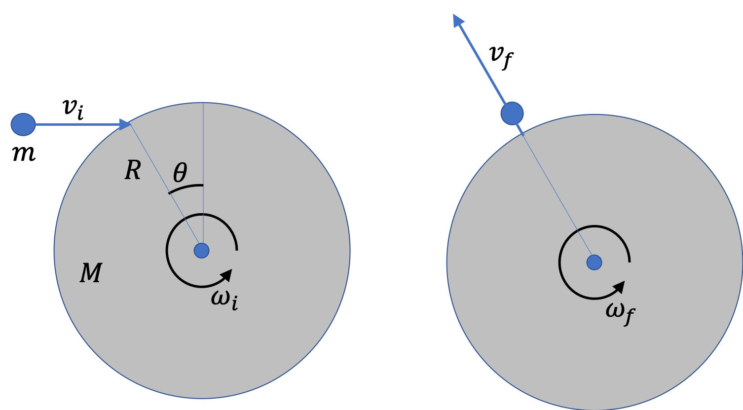
Figure 9.121 shows a ball of mass \(m\) striking a wheel of mass \(M \) and radius \(R\) and bouncing back in the drection away from the center of the wheel. Assume you are given, the angle \(\theta\text{,}\) \(v_i\text{,}\) and \(\omega_i\text{.}\) You do not need \(v_f\) in this geometry. You are to find \(\omega_f\text{.}\)
I would prefer you work with symbols, but if you want numerical values, you may use: \(m = 0.2\text{ kg}\text{,}\) \(M=5\text{ kg} \text{,}\) \(R=0.5\text{ m}\text{,}\) \(\theta = 30^{\circ}\text{,}\) \(v_i = 200\text{ m/s}\text{,}\) \(\omega_i = 10\text{ rad/s}\text{.}\)
Answer.
\(\omega_i - \dfrac{2 m v_i\cos\,\theta}{ M R}\text{,}\) \(17.7\text{ rad/s} \) in the clockwise sense.
Solution.
Consider a combined system of the ball and the wheel. Apply the conservation of angular momentum about the axis through the center of the wheel and perpendicular to the wheel. We also need to keep track of the directions since we will need to add angular momenta vectorially.
Initially, we have the angular momentum of the wheel to be
\begin{equation*}
L_{i}^{\text{wheel}} = \dfrac{1}{2}MR^2\, \omega_i,\ \ \ \text{(Counterclockwise)}
\end{equation*}
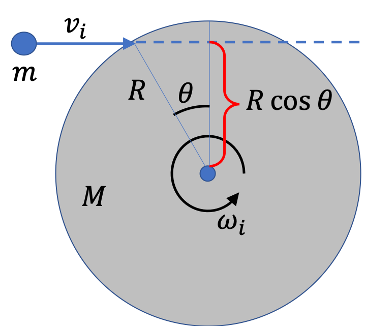
and the motion of the ball about this axis gives the angular momentum of the ball to be
\begin{equation*}
L_{i}^{\text{ball}} = m R\cos\,\theta, \ \ \ \text{(Clockwise)}
\end{equation*}
This is clear from the picture to the right.
For counterclockwise, we use positive, and for clockwise we use negative. Therefore, initially, we have the following net angular momentum.
\begin{equation*}
L_i = \dfrac{1}{2}MR^2\, \omega_i - m v_i R\cos\,\theta.
\end{equation*}
Now, the angular momentum of the ball is zero since its velocity line passes through the axis of rotation.
\begin{equation*}
L_{f}^{\text{ball}} = 0,
\end{equation*}
and the final angular momentum of the wheel will be
\begin{equation*}
L_{f}^{\text{wheel}} = \dfrac{1}{2}MR^2\, \omega_f.
\end{equation*}
Therefore, the final net angular momentum is
\begin{equation*}
L_f = \dfrac{1}{2}MR^2\, \omega_f.
\end{equation*}
Equating \(L_i \) to \(L_f\) and solving for \(\omega_f\) we get
\begin{equation*}
\omega_f = \omega_i - \dfrac{2 m v_i\cos\,\theta}{ M R}.
\end{equation*}
Now, using the numerical values we will get
\begin{equation*}
\omega_f =10 - \dfrac{2 \times 0.2 \times 200 \cos\,30^{\circ}}{ 5\times 0.5} = -17.7\text{ rad/s}.
\end{equation*}
The negative value means the wheel is now rotating in the clockwise sense.
