Section 38.8 Nonconservative Electric Field
A conservative field \(\vec G\) is a field whose line integral around any closed loop in space is zero.
\begin{equation}
\oint_{\text{any loop}}\vec G\cdot d\vec l = 0. \tag{38.26}
\end{equation}
A feild that is not conservative is called a nonconservative field. We have seen that the line integral of electric field of static charges around a loop just refers to voltage drop around the loop, which will always be zero in case of static electric field.
\begin{equation}
\oint_{\text{any loop}}\vec E \cdot d\vec l= 0\ \ \ \text{(static)} \tag{38.27}
\end{equation}
Therefore, static electric field is a conservative field. However, this is not the case for the dynamic electric field generated by changing magnetic flux. Instead, it obey’s Farady’s law.
\begin{equation}
\oint_{\text{any loop}}\vec E \cdot d\vec l= -\frac{d\Phi_B}{dt} \ \ \ \text{(dynamic)} \tag{38.28}
\end{equation}
Recall that the conservative nature of static electric field meant work per unit charge would be independent of path between two points in space. Using this result, we were able to introduce the concept of electric poential and deduce Kirchoff’s voltage law. This would not be possible in the dynamic electric field and Kirchoff’s voltage law would not apply. Instead, we must use Farady’s law, Eq. (38.28) as illustrated below.
Static Electric Field and Kirchoff’s Loop Law:
As an example of the consequences of the conservative electric field consider the simple circuit containing a battery of EMF, \(\mathcal{E_{\text{bat}}}\text{,}\) and a resistor of resistance, \(R\text{,}\) as shown in Figure 38.46. Battery sets up static electric field in the wire which drives the flow of current in the circuit.
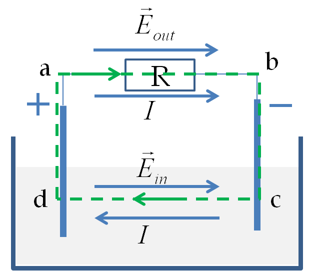
Notice that, in this circuit, the electric field of charges at the terminals goes from the positive terminal to the negative terminal of the battery, which is same as the direction of current in the resistor, but inside the battery, the electric field is in the opposite direction to the current.
Now, let us perform a line integral of the electric field around the loop of the circuit. When a line integral is done around a loop of the circuit, say in the direction of current all the way around, there are two contributions in this circuit, one in the resistor connected to the two terminals of the battery, which is positive, and one inside the battery, which is negative.
\begin{align*}
\amp \int_{a\text{-}b} \vec E \cdot d\vec l = IR\ \ \text{(Ohm's law)}\\
\amp \int_{b\text{-}c\text{-}d\text{-}a} \vec E \cdot d\vec l = -\mathcal{E_{\text{bat}}}\ \ \text{(Definition of battery EMF.)}
\end{align*}
Therefore, the integral around \(a\mbox{-}b\mbox{-}c\mbox{-}d\mbox{-}a\) loop is found to be:
\begin{equation*}
\oint \vec E \cdot d\vec l =IR - \mathcal{E_{\text{bat}}}.
\end{equation*}
Since the electric field in this situation is conservative, we set this to zero to obtain the relation between the voltage of the battery and the current in the circuit.
\begin{equation*}
\oint \vec E \cdot d\vec l = 0\ \ \Longrightarrow IR - \mathcal{E_{\text{bat}}}=0.
\end{equation*}
Nonconservative Electric Field and Faraday’s Law:
As an illustration of a nonconservative electric field consider the situation in Figure 38.47.
This is same as Figure 38.46 except that we now have an external magnetic field that is pointed out-of-page and increasing in magnitude.
In this setting, Faraday’s equation will replace Kirchhoff’s loop rule since magnetic flux though the loop varies with time.
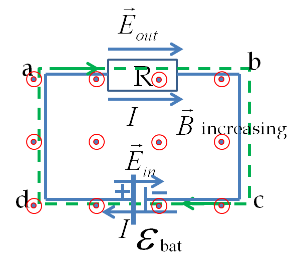
The equation for loop a-b-c-d-a is
\begin{equation}
IR - \mathcal{E_{\text{bat}}} = -\frac{d\Phi_B}{dt}. \tag{38.29}
\end{equation}
The right hand side of this equation is the induced EMF, \(\mathcal{E}_{\text{ind}}\text{.}\) Therefore, current in this circuit will depend on both the permanent EMF of the battery and the induced EMF of the changing magnetic flux.
\begin{equation}
I = \frac{\mathcal{E_{\text{bat}}} + \mathcal{E}_{\text{ind}}}{R}. \tag{38.30}
\end{equation}
