Logo image

Physics Bootcamp

Section 41.4 Capacitative AC Circuits

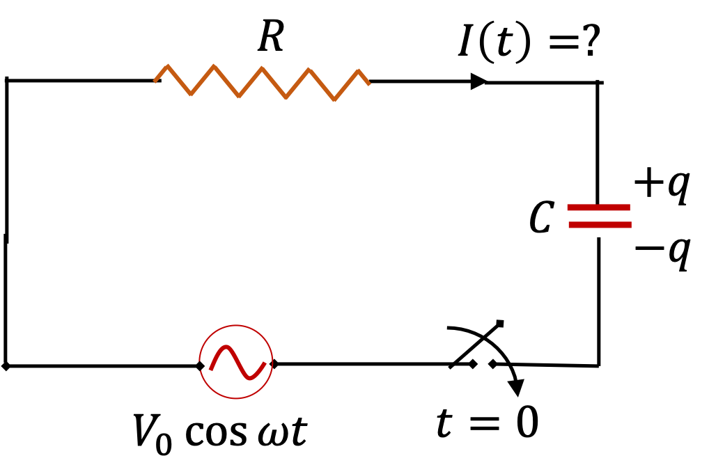
Every circuit has some capacitance due to the conductors of the circuit. By inserting a capacitor in the circuit you can always introduce significant capacitance in the circuit. These circuits will be called capacitative circuit. A simple example is provided by the RC-circuit in Figure 41.18.
Consider the circuit on the right with capacitance \(C\) and resistance \(R\) in series with an AC source with the following sinusoidal EMF.
\begin{equation} V(t) = V_0\cos(\omega t),\tag{41.23} \end{equation}
where I have chosen phase constant \(\phi_V=0\text{.}\) This will set the reference for phase comparisons with the current and other sinusoidal quantities.
Figure 41.18.
By applying Faraday’s law or Kirchhoff’s voltage rule to the loop of the circuit, we show in a Calculus section below that current in the circuit is
\begin{equation} I(t) = I_0 \cos(\omega t + \phi_I),\tag{41.24} \end{equation}
where amplitude and phase are given by
\begin{align} \amp I_0 = \frac{V_0}{\sqrt{R^2 + ( 1/\omega C )^2 }},\tag{41.25}\\ \amp \phi_I = \tan^{-1}\left(\dfrac{1}{\omega R C}\right).\tag{41.26} \end{align}
The quantity \(1/\omega\,C\) is the reactance \(X_C\) of the capacitor.
\begin{equation*} X_C = \frac{1}{\omega\,C}. \end{equation*}
Clearly, the influence of capacitor is reduced at higher frequencies. Furthermore, just as in the last section on \(RL\)-circuit, the ratio of the amplitude of voltage to that of current \(V_0/I_0\) is called impedance of the circuit, denoted by \(|Z|\text{.}\)
\begin{equation*} |Z| = \sqrt{R^2 + X_C^2 } = \sqrt{R^2 + \frac{1}{\omega^2\,C^2} }. \end{equation*}

Subsection 41.4.1 Series RC Circuit

Consider a circuit containing a resistor (\(R\)) and a capacitor (\(C\)) driven by a sinusoidal EMF as shown in the figure. Using voltage drops across each element, we get the following Faraday loop equation.
\begin{equation*} V_0\: \cos(\omega t) -\dfrac{1}{C}\int^t I(t') dt' - R I = 0. \end{equation*}
We will write this equation as
\begin{equation} \frac{dI}{dt} + \dfrac{1}{RC} I = -\dfrac{\omega V_0}{R}\, \sin(\omega t),\tag{41.27} \end{equation}
and seek the steady state solution in the form
\begin{equation*} I(t) = I_0\,\cos(\omega t + \phi_I). \end{equation*}
Using this in Eq. (41.27), expanding the trig functions, collecting coefficients of \(\sin(\omega t )\) and \(\cos(\omega t)\text{,}\) and solving for \(I_0\) and \(\phi_I\) give the desired result in a similar calculations as done in Section 41.3.
\begin{gather*} I_0 = \frac{V_0}{\sqrt{R^2 + ( 1/\omega C )^2 }} \\ \phi_I = \tan^{-1}\left(\dfrac{1}{\omega R C}\right) \end{gather*}

Remark 41.19. Impedance of an RC Circuit.

The ratio of the amplitude of the voltage of the source to that of the current through the source has units of resistance. However, this quantity here consists of the contributions from capacitance and frequency. This quantity “acts” like overall resistance in the circuit. Just as in the RL circuit, we call this ratio amplitude of the impedance of the circuit and denote it by \(|Z|\text{.}\)
\begin{equation} |Z| = \frac{\text{Amplitude of Voltage}}{\text{Amplitude of Current}} = \sqrt{R^2 + \left(1/\omega C\right)^2}.\tag{41.28} \end{equation}
The negative of the phase of overall current \(I(t)\) relative to the phase of the source emf gives the phase of impedance. Denoting this phase by \(\phi_Z\text{,}\) we have
\begin{equation} \phi_Z = -\tan^{-1}\left(\dfrac{1}{\omega R C}\right).\tag{41.29} \end{equation}

Remark 41.20. RC Circuit at High and Low Frequencies.

  1. High frequency ( \(\omega\ \rightarrow\ \infty\) Limit)
    As the frequency of the driving EMF is increased, the capacitative reactance becomes smaller. Therefore an RC-circuit becomes more and more like a purely resistive circuit as capacitance becomes less important. Basically, at high frequency the capacitor never gets a chance to charge to any significant extent. The current in the circuit will be in-phase with the EMF, i.e., \(\phi\ \rightarrow\ 0\text{,}\) and the amplitude \(I_0\) is obtained by ignoring the presence of capacitor, i.e., \(I_0\approx V_0/R\text{.}\)
  2. Low frequency ( \(\omega\ \rightarrow\ 0\) Limit)
    At low frequencies of the driving EMF, the capacitative reactance becomes large and the resistor becomes less and less important in an RC-circuit. The phase constant of the current reaches \(+\pi/2\) and the amplitude \(I_0\) is simply given by ignoring the resistance \(R\) in the circuit, \(I_0 \approx \omega C V_0\text{.}\)

Example 41.21. Capacitative Circuit Example.

A \(200\text{-}\mu\text{F}\) capacitor is connected across the terminals of a \(15\text{-V}\) AC source (i.e. \(V_\text{rms} = \frac{V_0}{\sqrt{2}} = 15\text{ V}\)) of frequency \(66\text{ Hz}\text{.}\) Assume zero resistance in the circuit. Find
  1. the reactance of the capacitor,
  2. the amplitude of impedance of the circuit,
  3. the current amplitude,
  4. the phase constant for current.
Answer.
(a) \(12.1\: \Omega \text{,}\) (b) \(12.1\: \Omega\text{,}\) (c) \(1.75\:\text{A}\text{,}\) (d) \(90^{\circ}\text{.}\)
Solution 1. a
Using formulas for the corresponding quantities we get
\begin{equation*} X_C = \dfrac{1}{2\pi f C} = \dfrac{1}{2\pi \times 66\:\text{Hz}\times 200\:\mu\text{F}} = 12.1\: \Omega. \end{equation*}
Solution 2. b
Since \(R=0\) we will get
\begin{equation*} |Z| = \sqrt{R^2 + X_C^2} = 12.1\: \Omega. \end{equation*}
Solution 3. c
\begin{equation*} I_0 = \dfrac{V_0}{|Z|} = \dfrac{\sqrt{2}\times 15\:\text{V}}{12.1\: \Omega} = 1.75\:\text{A}. \end{equation*}
Solution 4. d
Since \(R=0\) we will get
\begin{equation*} \phi_I = \tan^{-1}\left(\dfrac{X_C}{R} \right) = 90^{\circ}. \end{equation*}

Example 41.22. Current in a Capacitative Circuit with Varying Frequency.

A \(20\text{-}\mu\text{F}\) capacitor is connected across a \(10\text{-V}\) AC source (i.e., \(V_\text{rms} = 10\text{ V}\)) of variable frequency \(f\text{.}\) Find current amplitude in the circuit for the following values of \(f\text{.}\) Assume negligible resistance.
  1. \(\displaystyle 1.0 \text{ Hz}\)
  2. \(\displaystyle 10.0 \text{ Hz}\)
  3. \(\displaystyle 100.0 \text{ Hz}\)
  4. \(\displaystyle 1.0 \text{ kHz}\)
  5. \(\displaystyle 10.0 \text{ kHz}\)
  6. \(\displaystyle 100.0 \text{ kHz}\)
  7. \(\displaystyle 1.0 \text{ MHz}\)
  8. \(\displaystyle 1.0 \text{ GHz}\)
Answer.
  1. \(\displaystyle 1.77 \text{ mA}\)
  2. \(\displaystyle 17.7 \text{ mA}\)
  3. \(\displaystyle 178 \text{ mA}\)
  4. \(\displaystyle 1.78 \text{ A}\)
  5. \(\displaystyle 17.8 \text{ A}\)
  6. \(\displaystyle 178 \text{ A}\)
  7. \(\displaystyle 1.78 \text{ kA}\)
  8. \(\displaystyle 1.78 \text{ MA}\)
Solution.
The amplitude of the current in the circuit will be given by
\begin{equation*} I_0 = \dfrac{\sqrt{2}\:V_{\text{rms}}}{|Z|} = \sqrt{2}\:V_{\text{rms}}\times 2\pi\:f\:C. \end{equation*}
Using the values given in the problem we find the following for the frequency \(f\) Hz source.
\begin{equation*} I_0 = \sqrt{2}\:V_{\text{rms}}\times 2\pi\:f\:C = 1.777\: f\ \ [\text{units: mA}]. \end{equation*}
  1. \(\displaystyle 1.77 \text{ mA}\)
  2. \(\displaystyle 17.7 \text{ mA}\)
  3. \(\displaystyle 178 \text{ mA}\)
  4. \(\displaystyle 1.78 \text{ A}\)
  5. \(\displaystyle 17.8 \text{ A}\)
  6. \(\displaystyle 178 \text{ A}\)
  7. \(\displaystyle 1.78 \text{ kA}\)
  8. \(\displaystyle 1.78 \text{ MA}\)

Example 41.23. RC Circuit as a Low Pass Filter.

A low-pass filter is a circuit that lets out low-frequency electrical signals while suppressing high-frequency signals. The frequency above which signal drops significantly is called the cutoff frequency of the low-pass filter.
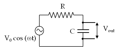
A series RC-circuit with an AC signal source, shown in Figure 41.24, can serve as a low pass filter if the output voltage is taken across the capacitor, the input voltage being the voltage of the source.
Figure 41.24.
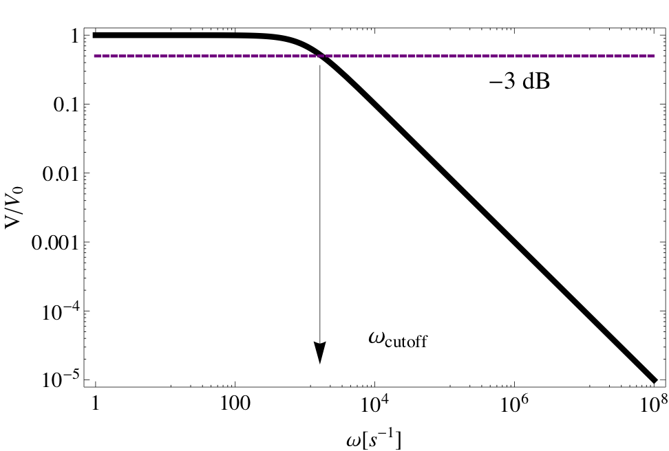
Consider a circuit containing a \(200\text{-}\Omega\) resistor and a \(50\text{-}\mu\text{F}\) capacitor in series with a \(18\text{-V}\) AC source of variable angular frequency \(\omega\text{.}\) (a) Determine the RMS-voltage across the capacitor (\(V_C\)) as a function of frequency, and (b) plot \(V_C/V_0\) versus \(\omega\) for \(R = 1000\:\Omega\) and \(C = 10^{-6}\:\text{F}\) and find the cutoff frequency.
Answer.
(a) \(\dfrac{V_0}{\sqrt{2}}\: \dfrac{1 }{\sqrt{1 + \omega^2R^2C^2}}\text{.}\) (b) See solution.
Solution 1. (a)
We need the reactance \(X_C\) and the impedance \(Z\) of the circuit to find the phase and amplitude of the current.
\begin{equation*} X_C = \dfrac{1}{\omega C},\ \ Z = \sqrt{R^2 + X_C^2} = \sqrt{R^2 + \frac{1}{\omega^2C^2}}. \end{equation*}
Therefore, the amplitude and phase of the current in the circuit are
\begin{equation*} I_0 = \dfrac{V_0}{Z} = \dfrac{V_0\:\omega C}{\sqrt{1 + \omega^2R^2C^2}},\ \ \tan \phi = \dfrac{1}{\omega RC} \end{equation*}
The oscillating current is \(I(t) = I_0\:\cos(\omega t + \phi)\text{.}\) Since the voltage across the capacitor lags the current by \(\pi/2\) we get the following expression for the voltage \(V_C\) across the capacitor will be
\begin{equation*} V_C = I_0\:X_C\:\cos\left(\omega t + \phi - \frac{\pi}{2}\right). \end{equation*}
This gives the following for the RMS-voltage across the capacitor.
\begin{align*} V_{\text{C,rms}} \amp = \dfrac{1}{\sqrt{2}}\:I_0\:X_C \\ \amp = \dfrac{1}{\sqrt{2}}\: \dfrac{V_0\:\omega C}{\sqrt{1 + \omega^2R^2C^2}}\: \dfrac{1}{\omega C}\\ \amp = \dfrac{V_0}{\sqrt{2}}\: \dfrac{1 }{\sqrt{1 + \omega^2R^2C^2}}. \end{align*}
Solution 2. (b)
In Figure 41.25 we plot \(V/V_0\) versus \(\omega\) for \(R = 1000\:\Omega\) and \(C = 10^{-6}\:\text{F}\text{.}\) The time constant for this circuit will be \(\tau = RC = 10^{-3}\:\text{s}\text{.}\) It is seen that the output of the circuit drops to half the amplitude if the frequency goes beyond the cutoff frequency \(f_{\text{cutoff}} = \omega_{}/2\pi \approx 276\:\text{Hz}\text{.}\)
Figure 41.25.

Example 41.26. RC Circuit as a High Pass Filter.

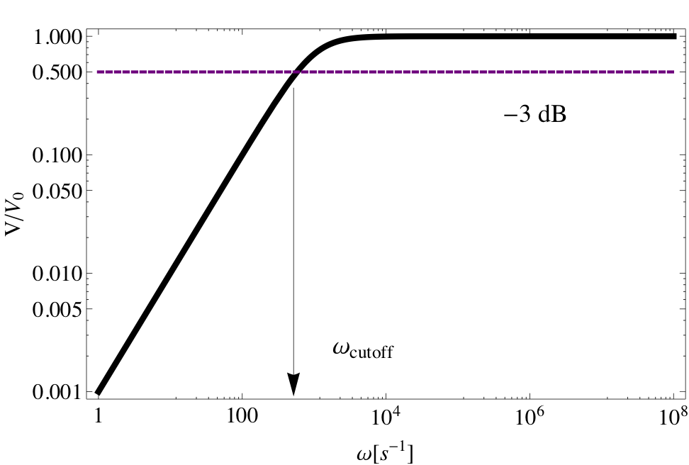
A high-pass filter is a circuit that lets out high-frequency electrical signals while suppressing low-frequency signals. The frequency above which signal becomes significant is called the cutoff frequency of the high-pass filter.
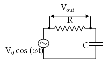
A series RC-circuit with an AC signal source, shown in Figure 41.27, can serve as a high-pass filter if the output voltage is taken across the resistor, the input voltage being the voltage of the source.
Figure 41.27.
Consider a circuit containing a \(200\text{-}\Omega\) resistor and a \(50\text{-}\mu\text{F}\) capacitor in series with a \(18\text{-V}\) AC source of variable angular frequency \(\omega\text{.}\) (a) Determine the RMS-voltage across the capacitor (\(V_C\)) as a function of frequency, and (b) plot \(V_C/V_0\) versus \(\omega\) for \(R = 1000\:\Omega\) and \(C = 10^{-6}\:\text{F}\) and find the cutoff frequency.
Answer.
(a) \(\dfrac{V_0}{\sqrt{2}}\: \dfrac{\omega R C }{\sqrt{1 + \omega^2R^2C^2}}\text{,}\) (b) See solution.
Solution 1. (a)
We need the reactance \(X_C\) and the impedance \(Z\) of the circuit to find the phase and amplitude of the current.
\begin{equation*} X_C = \dfrac{1}{\omega C},\ \ Z = \sqrt{R^2 + X_C^2} = \sqrt{R^2 + \frac{1}{\omega^2C^2}}. \end{equation*}
Therefore, the amplitude and phase of the current in the circuit are
\begin{equation*} I_0 = \dfrac{V_0}{Z} = \dfrac{V_0\:\omega C}{\sqrt{1 + \omega^2R^2C^2}},\ \ \tan \phi = \dfrac{1}{\omega RC} \end{equation*}
The oscillating current is \(I(t) = I_0\:\cos(\omega t + \phi)\text{.}\) Since the voltage across the resistor is in phase with the current we get the following expression for the voltage \(V_R\) across the resistor will be
\begin{equation*} V_R = I_0\:R\:\cos\left(\omega t + \phi \right). \end{equation*}
This gives the following for the RMS-voltage across the capacitor.
\begin{align*} V_{\text{R,rms}} \amp = \dfrac{1}{\sqrt{2}}\:I_0\:R \\ \amp = \dfrac{1}{\sqrt{2}}\: \dfrac{V_0\:\omega R C}{\sqrt{1 + \omega^2R^2C^2}}\\ \amp = \dfrac{V_0}{\sqrt{2}}\: \dfrac{\omega R C }{\sqrt{1 + \omega^2R^2C^2}}. \end{align*}
Solution 2. (b)
In Figure 41.28 we plot \(V_R(\text{rms})/V_0(\text{rms})\) versus \(\omega\) in a log-log plot for \(R = 1000\:\Omega\) and \(C = 10^{-6}\:\text{F}\text{.}\) It is seen that the output of the circuit drops to half the amplitude if the frequency goes below the cutoff frequency \(f_{\text{cutoff}} = \omega_{\text{cutoff}}/2\pi \approx 92\:\text{Hz}\text{.}\)
Figure 41.28.

Exercises 41.4.2 Exercises

1. Capacitance of a Starter of a Fluorescent Light Bulb from Current and Voltage.

A starter for a fluorescent light bulb is a capacitor. When an AC voltage \(170\; \text{V}\; \cos(2\pi\times 60 \times t)\) is applied across the capacitor, a peak current of \(1.2\,\text{A}\) flows in the capacitor. What is the capacitance?
Hint.
Use \(I_0 = V_0/|Z|\text{.}\)
Answer.
\(18.7\:\mu\text{F}\text{.}\)
Solution.
Using \(I_0 = V_0/|Z| = V_0\omega C\text{,}\) we obtain
\begin{align*} C \amp = \dfrac{I_0}{2\pi\:f\:V_0} \\ \amp = \dfrac{1.2\:\text{A}}{2\pi\:60\:\text{Hz}\times 170\: \text{V}} = 18.7\:\mu\text{F}. \end{align*}