20.Interference on Road Trip for Electromagnetic Wave.
Two radio antennas are \(0.5\text{ km}\) apart. They broadcast \(4\text{ MHz}\) signals in phase. A car travels on a road parallel to the line joining the two antennas. The road is \(20\text{ km}\) away from the antennas, i.e. the length of a line perpendicular to both the line joining the antennas and the road is \(12\text{ km}\text{.}\) When the car moves on the road at a constant speed the net signal increases and decreases periodically. State why one would observe such variation in the intensity and determine five successive places on the road the strongest signals will be found and four successive places where the weakest signals will be found.
This is just Young’s double-slit experiment, excpet that now, frequency is in rado wave, instead of visible light range. Let’s calculate the wavelength since we can then use the condition from douoble-slit directly.
\begin{equation*}
d\sin\theta_m = m \lambda.
\end{equation*}
Let \(y\) axis is placed along the road with origin at the center. Let \(L\) is the distance to the road. Then, we can write this in small angle approximation as
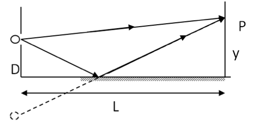
A Lloyd’s mirror is a set up that allows a double-slit experiment with only one source by placing a mirror between the slit and the screen as shown in Figure 47.35. Note that in this setup, the virtual image of the original source serves as the second source of light.
(a) Find the conditions for constructive and destructive interferences on the screen if the screen is a distance L away and the slit is a distance \(D\) above the mirror.
(b) If \(L = 2.5\text{ m}\text{,}\)\(D = 20\ \mu\text{m}\) and wavelength of light used is the yellow sodium D line of wavelength \(589\text{ nm}\text{,}\) find \(y\) coordinates of two places on the screen you will find bright spots and two places where there will be dark spots. Use the simplification that comes with the approximation that \(D\lt\lt L\text{.}\)
(a) and (b) There is a phase changing event in one of the paths relative to the other path. Maky necessary modification to the condition for Young’s double-slit formula for constructive and destructive interferences.
(a) Constructive Interferences. The geometry of the Lloyd’s mirror is similar to Young’s double slit experiment with separation between the slits \(d = 2D\) with one exception: one of the paths has a additional phase shift of \(pi\) rad due to the reflection in that path. Therefore, the condition for constructive interference will be what was the condition of destructive interference in the Young’s double-slit experiment, viz.,
22.Signal Intensity Picked up by Airplane Varying Intensity due to Interference.
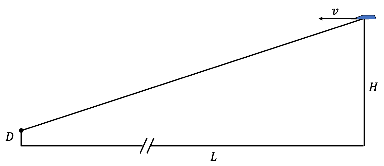
A radio transmitter atop a \(50\text{-m}\) tall tower near a large lake emits a monochromatic electromagnetic wave of frequency \(110\text{ MHz}\text{.}\) An airplane flying \(20\text{ km}\) away and \(6,000\text{ m}\) above ground finds the signal from the tower to vary in intensity with a period of \(18\text{ sec}\text{.}\) How fast is the plane flying with respect to the ground?
Work out condition for \(m^\text{th}\) order interference using Lloyd’s mirror example, Exercise 47.7.21. Cast the expression in terms of horizotal distance, calling it \(l_m\text{.}\) Then equate \(|l_\text{next order} - l_{this order}| = vT\text{.}\)
The varying signal occurs due to Lloyd effect addressed in the Exercise 47.7.21. There are two signals that reach the airplane, one direct and the other reflected from the ground as shown in Figure 47.37.
The constructive interference condition for \(m^\text{th}\) constructive interference will be
\begin{equation*}
d \sin\theta_m = m \frac{\lambda}{2},\ \ m\text{ odd integer}.
\end{equation*}
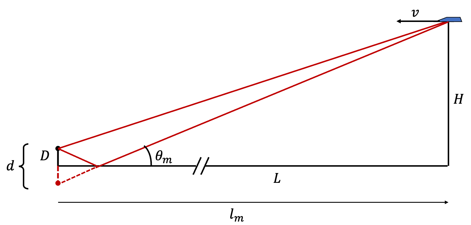
Here \(d=2D\) with \(D\) equal to the height of the tower. Since \(H/L=0.3\text{,}\) the angles will be around \(16^\circ\text{.}\) Therefore, we will use small angle approximations, such as \(\sin\theta\approx\tan\theta=y/L\text{.}\)
Let us denote the horizontal distance where \(m^\text{th}\) order occurs by \(l_m\text{.}\) We are going to write \(l_{m+2}\) also, and then equate \(|l_{m+2}-l_m\) to \(vT\) with \(T\) the period observed. From the interference condition for order \(m\) we have
\begin{equation*}
\frac{H}{l_m} = m \frac{\lambda}{4D},\ \ m\text{ odd integer}.
\end{equation*}
Therefore, next order will be at \(m+2\) since \(m\) is restricted to odd integers.
Three waves of identical wave amplitude \(E_0\text{,}\) and identical wavelength \(\lambda\) start in phase at the plane shown in the figure with a dashed line. The waves interfere at a screen and we wish to find a formula for the intensity on the screen in terms of the intensity in a single wave. What would be the net intensity at the symmetric point shown in the figure? Assume \(L \gg d\)
Let the electric fields of the three waves be approximately parallel at P. Then, by using the superposition principle for electric fields, we get the following net electric field at P.
Let \(l_1\text{,}\)\(l_2\) and \(l_3\) be the distance traveled by the three waves from the source to the place they meet. You can find \(l_i\)’s from the geometry given. Since they start out in-phase the expressions for the electric fields will be
\begin{equation*}
\vec E_i = \vec E_0\:\cos(\omega t - k l_i),\ \ i = 1, 2, 3,
\end{equation*}
where \(\omega\) is the angular frequency, \(k\) is the wavenumber, and \(\vec E_0\) the amplitude of the wave. Now, the intensity at P will be based on the net electric field.
where \(\langle\cdots\rangle\) stands for time averaging. We introduce the electric field expressions here, expand the expression, and compute time average of each term to obtain the final result. To write the answer compactly we introduce the notation, \(\Delta_{ij} = k\left| l_i - l_j\right|\text{,}\) which stands for the phase difference between waves \(i\) and \(j\text{.}\)
Three waves of identical wave amplitude \(E_0\text{,}\) and identical wavelength \(\lambda\) are in phase at the plane shown in the figure with a dashed line. Find a formula for the intensity of light at the arbitrary point in terms of angle \(\theta\text{,}\) assuming \(\theta \ll 1\) when expressed in radians. This exercise is an extension of the previous exercise.
25.Placing Plastic Over one Slit of a Two-Slit Experiment.
When you place a plastic tape over one of the slits of a double-slit experiment you find that the constructive and destructive interferences occur at different places than before. How much would the \(m = 1\) constructive interference for a green light of wavelength \(530\, \text{nm}\) in air move on the screen of a Young’s double-slit experiment that is one meter away with the slits \(5\, \mu\text{m}\) apart if one of the slits is covered with a plastic tape of refractive index \(1.5\) and thickness \(2\, \mu\text{m}\text{?}\)