Logo image

Physics Bootcamp

Section 41.6 Power in AC Circuits

Subsection 41.6.1 Power of an AC Source Driving an RLC Circuit

The instantaneous power \(P\) of any circuit element is obtained by the product of the current through the element and the voltage across the element. Thereofore, power of the driving EMF would be equal to the product of its voltage \(V(t)\) and current \(I(t)\) through it.
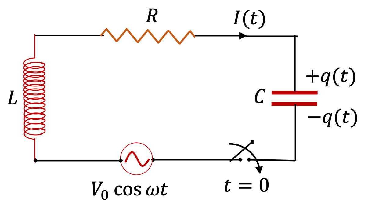
In a series RLC circuit (Figure 41.31) with source voltage \(V(t) = V_0\,\cos(\omega t)\text{,}\) the steady current steady state current is \(I=I_0\,\cos(\omega t + \phi_I) \text{,}\) with
\begin{align*} \amp I_0 = \dfrac{V_0}{\sqrt{R^2 + \left(\omega L - \dfrac{1}{\omega C} \right)^2}},\\ \amp \tan\,\phi_I = \dfrac{1}{\omega RC} - \dfrac{\omega L}{R}. \end{align*}
Figure 41.31.
Therefore, power of the source in this circuit at an arbitray insant \(t\) is
\begin{equation*} P(t) = I(t) V(t) = I_0 V_0 \cos(\omega t)\cos(\omega t +\phi_I). \end{equation*}
The instantaneous power is time-dependent. The average power \(P_{\text{ave}}\) obtained from \(P(t)\) by averaging the later over a complete cycle is often of more interest that the instantaneous power \(P(t)\text{.}\) The average power of the source is sometimes called the apparent power. The product of cosines in \(P(t)\) can be rewritten as sum of cosines.
\begin{equation*} P(t) = \dfrac{I_0 V_0}{2} \left[ \cos(2\omega t + \phi_I) + \cos\,\phi_I \right]. \end{equation*}
The average of \(\cos(2\omega t+ \phi_I)\) over a period will be zero. Therefore \(P_{\text{ave}}\) is
\begin{equation*} P_{\text{ave}} = \dfrac{I_0 V_0}{2}\: \cos\,\phi_I, \end{equation*}
where
\begin{equation} \cos\,\phi_I = \dfrac{R}{\sqrt{R^2 + \left(\omega L - \dfrac{1}{\omega C} \right)^2}}.\tag{41.40} \end{equation}
is called the power factor of the AC circuit. In purely resistive circuits, i.e, in the absence of inductor and capacitor, the power factor is 1. The power factor is important in highly inductive circuits, such as circuits with motors, compressors, and transformers, and in circuits at high frequency.
When the circuit is driven at the resonance frequency \(\omega = \omega_R\text{,}\) with \(\omega_R = 1/\sqrt{LC}\text{,}\) the power factor will also equal to 1, the maximum value. Therefore, in high inductive circuits it is common practice to insert appropriate capacitative elements so as to make the power factor as close to 1 as possible.

Remark 41.32. RMS Current and Voltage.

From the voltage \(V(t\)) and the current \(I(t)\) we can construct time-averaged quantities. The time averages of \(V(t)\) and \(I(t)\) are zero. However, if we do the time averaging after squaring them then we get a non-zero value, called the root-mean squared \(V_{\text{rms}}\) and \(I_{\text{rms}}\) as follows.
\begin{equation*} V_{\text{rms}} = \sqrt{\langle V(t)^2 \rangle} = \frac{V_0}{\sqrt{2}} \end{equation*}
\begin{equation*} I_{\text{rms}} = \sqrt{\langle I(t)^2 \rangle} = \frac{I_0}{\sqrt{2}} \end{equation*}
where \(\langle \cdots \rangle\) stands for time averaging operation. The average power of the source voltage is often expressed in terms of the \(V_{\text{rms}}\) and \(I_{\text{rms}}\) and the power factor as follows.
\begin{equation*} P_{\text{ave}} = V_{\text{rms}}\; I_{\text{rms}} \; \cos(\phi_I). \end{equation*}

Remark 41.33. Meaning of the Power Factor.

We find that the power of the source disappears when the resistance in the circuit is zero. Thus a purely reactive circuit does not use any energy. But you need a current for a reactive device such as a motor to function. Therefore, although no energy is used by a purely reactive device, the power supply company must supply a current to it. The product \(\left(V_{\text{rms}}.I_{\text{rms}}\right)\) is sometimes called the real power for which the power supplier must charge the power user, and not just the apparent power. The power factor is the ratio of the power of the source, i.e. the “apparent power”, to the actual power used in the resistor, i.e., the “real power”.
\begin{equation*} \text{Power Factor} = \frac{\text{Apparent Power}}{\text{Real Power}}. \end{equation*}
The power factor therefore gives a measure of the reactive part of the power usage. The power factor should be maximized so as to make the delivery of power more efficient. The power factor of a circuit with large inductors can be increased by adding a capacitor to the circuit as you can see from Eq. (41.40).

Example 41.34. Real Power, Apparent Power, and Power Factor of a Capacitative AC Circuit.

A \(200\text{-}\mu\text{F}\) capacitor is connected across the terminals of \(15\text{-V}\) AC source (i.e. \(V\textrm{rms} = 15\,\text{V}\)) of frequency \(66\, \text{Hz}\text{.}\) Assume negligible resistance in the circuit. Find (a) the real power, (b) the power factor, and (c) the apparent power.
Solution 1. a
Real power is given by
\begin{align*} \amp I_{\textrm{rms}} V_{\textrm{rms}} \\ \amp \quad = \dfrac{I_0}{\sqrt{2}} V_{\textrm{rms}}\\ \amp = \dfrac{1.75\:\textrm{A}}{\sqrt{2}}\times 15\:\textrm{V} = 18.6\: \textrm{V.A} \end{align*}
Solution 2. b
Power factor = \(\cos (\phi) = 0\text{.}\)
Solution 3. c
Apparent power = real power \(\times\) power factor = 0.

Example 41.35. Power Factor of a Large Motor.

An AC circuit has a large motor, modeled as a resistance of \(100\; \Omega\) and inductance of \(8\text{ H}\) in series connected to a \(120\text{ V }\) (rms) AC line that fluctuates at a \(60\text{ Hz}\) frequency. Find (a) the amplitude of the impedance of the circuit, (b) the peak voltage, (c) RMS current, (d) the power factor, (e) real power, and (f) apparent power.
Answer.
(a) \(318\; \Omega\text{,}\) (b) \(169.7\;\text{V}\text{,}\) (c) \(0.377\; \text{A} \text{,}\) (d) \(0.31\text{,}\) (e) \(45.2\; \text{W}\text{,}\) (f) \(14\; W\text{.}\)
Solution 1. a
This is simply a numerical example for an RL circuit and we can use the formulas already derived for that circuit. The amplitude of the impedance of the circuit is
\begin{align*} |Z| \amp = \sqrt{R^2 + (\omega L)^2}\\ \amp = \sqrt{(100\; \Omega)^2 + (2\pi\times 60\; \text{Hz}\times 8\; \text{H})^2} = 318\; \Omega. \end{align*}
Solution 2. b
Peak Voltage is,
\begin{equation*} V_{\text{peak}} = \sqrt{2} \times V_{\text{rms}} = \sqrt{2}\times 120\;\text{V} = 169.7\;\text{V}. \end{equation*}
Solution 3. c
RMS current is
\begin{equation*} I_{\text{rms}} = \frac{V_{\text{rms}}}{|Z|} = \frac{120\; \text{rms}}{318\; \Omega} = 0.377\; \text{A}. \end{equation*}
Solution 4. d
The power factor will be
\begin{equation*} \cos\, \phi_I = \frac{R}{Z} = \frac{100\;\Omega}{318\; \Omega} = 0.31. \end{equation*}
Solution 5. e
The real power will be
\begin{equation*} I_{\text{rms}} . V_{\text{rms}} = 0.377\; \text{A}\times 120\; \text{V} = 45.2\; \text{W}. \end{equation*}
Solution 6. f
The apparent Power will be
\begin{equation*} I_{\text{rms}} V_{\text{rms}} \cos(\phi)= 45.2\; \text{W}\times 0.31 = 14\; W. \end{equation*}
Although the unit Volt.Amp(V.A) is equal to unit Watt (W), one expresses the apparent power in VA and the real power in W. Note that the apparent power is what is happening as far as energy conservation is concerned, and the real power is what a utility company bases its charges on.

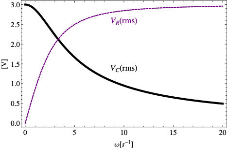
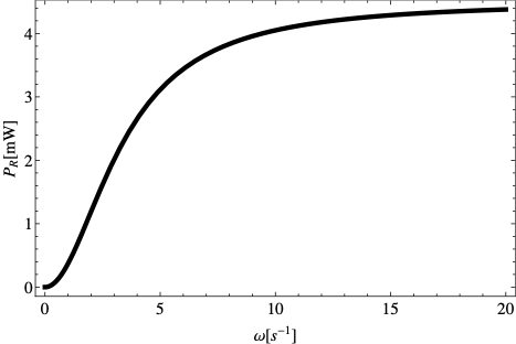
Example 41.36. Plot Voltages Across Resitor and Capacitor Versus Frequency.

A \(150\text{-}\mu\text{F}\) capacitor is connected in series to a \(2\text{-k}\Omega\) resistor and a \(3\text{-V}\) AC source (i.e. \(V\textrm{rms} = 3\, \text{V}\)) of variable frequency \(\omega\,\text{sec}^{-1}\text{.}\)
  1. Plot the RMS-voltage across the capacitor versus \(\omega\text{.}\)
  2. Plot the RMS-voltage across the resistor versus \(\omega\text{.}\)
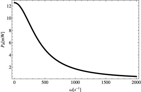
  3. Plot power delivered to the resistor versus \(\omega\text{.}\)
Solution 1. a,b
Figure 41.37.
Solution 2. c
Figure 41.38.

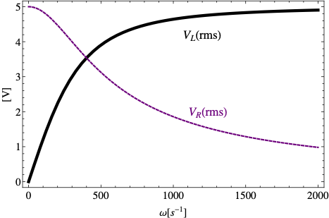
Example 41.39. Plot Voltages Across Resitor and Inductor Versus Frequency.

A \(5\text{-H}\) inductor of negligible internal resistance is connected across a \(2\text{-k}\Omega\) resistor and a \(5\text{-V}\) AC source (i.e. \(V\textrm{rms} = 5\, \text{V}\)) of variable frequency \(\omega\,\text{sec}^{-1}\text{.}\)
  1. Plot voltage across the inductor versus \(\omega\text{.}\)
  2. Plot voltage across the resistor versus \(\omega\text{.}\)
  3. Plot power delivered to the resistor versus \(\omega\text{.}\)
Solution 1. a,b
Figure 41.40.
Solution 2. c
Figure 41.41.

Exercises 41.6.2 Exercises

1. Power in an AC RLC Circuit.

A \(200\text{-}\Omega\) resistor, \(150\text{-}\mu\text{F}\text{,}\) and \(2.5\text{-H}\) inductor are connected in series with an AC source of amplitude \(10\, \text{V}\) and variable angular frequency \(\omega\text{.}\)
  1. What is the value of the resonance frequency, \(\omega_R\text{?}\)
  2. What is the amplitude of the current if \(\omega= \omega_R\text{?}\)
  3. What is the phase constant of the current when \(\omega= \omega_R\text{?}\) Is it leading or lagging the source voltage?
  4. Write voltage drops across resistor, inductor and capacitor, and the source voltage as a function of time when \(\omega= \omega_R\text{.}\)
  5. What is the power factor of the circuit when \(\omega= \omega_R\text{?}\)
  6. How much energy is used up by the resistor in \(2.5\, \text{s}\) when \(\omega= \omega_R\text{?}\)
Solution 1. a
\(\omega_R = \dfrac{1}{\sqrt{LC}} = 51.6\:\textrm{sec}^{-1}\text{.}\)
Solution 2. b
When \(\omega = \omega_R\text{,}\) we get \(I_0 = V_0/R\text{.}\) Putting in the numbers yields \(I_0 = 10/51.6 = 50\:\textrm{mA}\text{.}\)
Solution 3. c
\(\phi = 0\) since the lag and lead are perfectly balanced when \(\omega = \omega_R\text{.}\)
Solution 4. d
Let us compute the reactances first. \(X_L = \omega L = 129\:\Omega\) and \(X_C = 1/\omega C = 129\:\Omega\text{.}\) Therefore
\begin{align*} \amp V_R(t) = (50\:\textrm{mA}\times R)\:\cos( 51.6\: t) = (10\:\textrm{V})\:\cos( 51.6\: t)\\ \amp V_L(t) = (50\:\textrm{mA}\times X_L)\:\cos\left(51.6\: t +\frac{\pi}{2}\right) = (6.45\:\textrm{V})\:\cos\left(51.6\: t +\frac{\pi}{2}\right)\\ \amp V_C(t) = (50\:\textrm{mA}\times X_C)\:\cos\left(51.6\: t -\frac{\pi}{2}\right) = (6.45\:\textrm{V})\:\cos\left(51.6\: t -\frac{\pi}{2}\right)\\ \amp V(t) = (50\:\textrm{mA}\times Z)\:\cos\left(51.6\: t \right)= (10\:\textrm{V})\:\cos\left(51.6\: t \right) \end{align*}
Solution 5. e
\(\cos\phi = 1\text{.}\)
Solution 6. f
\begin{equation*} E = P_{\textrm{ave}}\times \Delta t = \frac{1}{2} I_0^2\:R\Delta t = 0.5\times 0.05^2\times 200\times 2.5 = 0.625\:\textrm{J} \end{equation*}

2. Power Dissipation in an AC RLC Circuit.

A resistor R (200 \(\Omega\)), a capacitor C (20 pF) and an inductor L (30 mH) are connected in parallel to an AC voltage source \(V_0\; \cos(\omega t)\) with \(V_0\) = 256 V and \(\omega\) = 120 rad per sec. (a) Find complex impedance of the circuit. (b) Find current in each branch. (c) Find the power factor. (d) Find the power dissipated.
Solution 1. a
Let us do this problem in the complex notation. The inverse of the net impedance for parallel circuit will be
\begin{equation*} \dfrac{1}{Z} = \dfrac{1}{R} + i\omega C - \dfrac{i}{\omega L}. \end{equation*}
For the given numerical values we obtain
\begin{equation*} Z = 0.647\:\Omega\angle 1.55\:\textrm{rad}. \end{equation*}
Solution 2. b
Therefore, the total current through the source will be
\begin{equation*} I = \dfrac{256\:\textrm{V}}{0.647\:\Omega}\:\cos(\omega t - 1.55) = (396\:\textrm{A})\:\cos(\omega t - 1.55). \end{equation*}
The current through the resistor will have the same phase as the EMF across the resistor, which is equal to the EMF of the source here.
\begin{equation*} I_R = \dfrac{256\:\textrm{V}}{200\:\Omega}\:\cos(\omega t) = (1.28\:\textrm{A})\:\cos(\omega t). \end{equation*}
The current through the capacitor will have the phase that would lead the phase of the EMF by \(\pi/2\text{.}\)
\begin{equation*} I_C = 256\:\times 120\times 20\times 10^{-12}\:\cos(\omega t + \pi/2) = (0.61\:\mu\textrm{A})\:\cos(\omega t+\pi/2). \end{equation*}
The current through the inductor will have the phase that would lag the phase of the EMF by \(\pi/2\text{.}\)
\begin{equation*} I_C = \dfrac{256\:\textrm{V}}{120\times 0.030 \:\Omega}\:\cos(\omega t-\pi/2) = (71.1\:\textrm{A})\:\cos(\omega t-\pi/2). \end{equation*}
Solution 3. c
The power factor of the circuit will be \(\cos\phi = \cos(1.55\:\textrm{rad}) = 0.02\text{.}\) \noindent (d) The power dissipated in the resistor will be \(\dfrac{1}{2}I_{0R}^2 R = \dfrac{1}{2}\times(1.28\:\textrm{A})^2\times 200\:\Omega = 164\:\textrm{W}\text{.}\)