In 1899 Marie Fabry and Jean Perot in France built an interferometer which used multiple beams by coating the two sides partially with a highly reflecting material. They found that multiple reflections resulted in much narrower interference fringes than other interferometers. It is widely used for precision spectroscopy, and as a gas laser cavity, among other things.
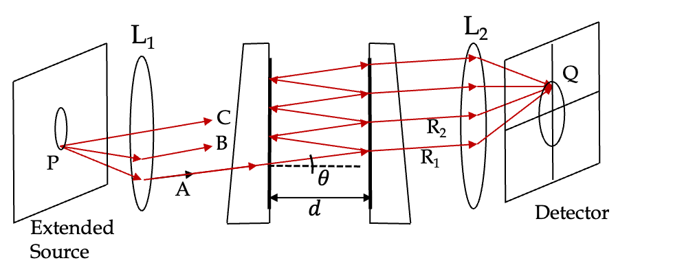
A Fabry-Perot interferometer shown in Figure 47.27 essentially consists of two parallel plates of glass whose inner surfaces are polished to a very high degree of flatness, and then coated with a highly reflecting thin film of silver or aluminum or some similarly good reflector. The outer surface of these plates are ground to make a wedge shape so that light escaping the cavity between the plates does not reflect back in. The distance \(d\) between plates can vary from a few millimeters to a few centimeters. Rays of light from an extended source enter the space between the reflecting plates, and emerge on both sides after each reflection. The rays emerging on the opposite end to the side of entrance are focused on a screen.
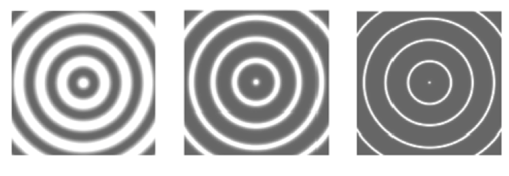
The extended light source, such as a mercury lamp is placed at the focal plane of a converging lens \(\text{L}_1\) so that the rays coming from a single point of the source emerge parallel on the other side of the lens at a particular angle of inclination. The transmitted rays from rays of same angle of inclination enter the space between the two partial reflectors. focus on the same point in the focal plane of lens \(\text{L}_2\text{.}\) For instance, the three rays A, B and C from the source point P shown in the figure converge at the same point Q on the screen. The rays from points on the light source in a circle that contains P meet in a circle on the screen. If the condition at Q is met for a constructive interference, we will see a bright ring, while if the condition there corresponds to a destructive interference, there will be a dark ring there. The interference pattern on the screen will have alternating bright and dark rings. The reflectivity \(r\) of the coating can be adjusted to sharpen the rings as illustrated in Figure 47.28.
Subsection47.6.1Interference Condition in Fabry-Perot Interferometer
In Fabry-Perot interfermoter, its an infinte collection of waves that interfere. When we have only two waves as in Subsection 47.3.1, we saw that the condition depended on phase difference \(\Delta_{12}\) between the two waves. There, we had concluded that if \(\Delta_{12}\) is an integral multiple of \(2\pi\text{,}\) then we will have constructive interference.
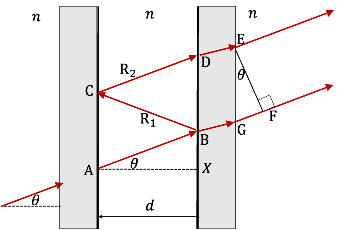
To figure out an expression of phase difference \(\Delta_{12}\text{,}\) we analyze the optical paths as we did in Subsection 47.3.1, of two succesive rays, shown as \(\text{R}_1\) and \(\text{R}_1\) in Figure 47.29.
Figure47.29.Geometry of Fabry-Perot for phase difference calculation between the successively transmitted wave. The phase difference comes from path difference of ABCDE and ABGF. Path ABCDE has two phase flipping reflections, one at B and the other at C, which make the net phase change due to reflection equal to \(2\pi\text{.}\)
Let \(\lambda\) be the wavelength in the medium of Fabry Perot. Now, we know that phase changes by \(2\pi\) radians when OPL changes by one wavelength, therefore, the phase difference between the two successive paths will be
Demanding this to be equal to \(2m\pi\) with \(m\) integers for constructive and equal to \(m^\prime\pi\) with \(m^\prime\) odd integers we get the interference conditions. Multiplying both sides by \(\lambda/2\pi\) we will write them as follows.
\begin{align}
\amp \text{Constructive: }\ \ 2 n d \cos\theta = m \lambda \ \ (m\ \text{ integer})\tag{47.46}\\
\amp \text{Destructive: }\ \ 2 n d \cos\theta = m^\prime \lambda \ \ (m^\prime\ \text{ odd})\tag{47.47}
\end{align}
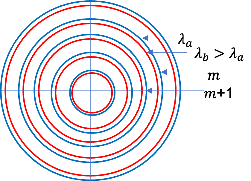
That is, higher order interference are more towards the center of the Fabry Perot patterns. Similarly, in the same order, higher wavelength will be towards the center.
Subsection47.6.2Intensity of Trnasmitted Waves in Fabry Perot
A more complete understanding of the wave interference in Fabry Perot interferometer requires examining the actual electromagnetic waves as we did when we studied the Fresnel equations for reflection and transmission in Subsection 46.4.1. That work is a little bit beyond the scope of this book. Even so, it is important to discuss implications of the results since Fabry Perot is used in many applications.
Let \(R\) be the reflectance of the surfaces on the two sides of the cavity. Let \(I_t\) be the intensity transmitted and \(I_i\) the incident intensity. Let \(\Delta_{12}\) be the phase difference between two successive waves in direction \(\theta\) as given in Eq. (47.45). The, the transmittance can be shown to be
\begin{equation}
T \equiv \frac{I_t}{I_i} = \frac{1}{1 + F \sin^2(\Delta_{12}/2)},\tag{47.48}
\end{equation}
where \(F\) is called the finesse coefficient or quality factor. Finesse coefficient is a function of the reflectance.
\begin{equation*}
F = \frac{4R}{(1-R)^2}.
\end{equation*}
Since \(0\le R \le 1.0\text{,}\)\(F\) is highly nonlinear. Typically, \(R\) is in the \(0.90\text{ to } 0.98\) range. That corresponds to \(F\) in range \(360 \text{ to } 9,800\text{.}\) With large finesse in Eq. (47.48), transittance becomes highly sensitive to \(\Delta\text{,}\) giving sharp peaks when plotted against \(\Delta_{12}\) or \(\theta\text{.}\)
The maxima and minima of transmittance in Eq. will correspond to the constructive and destructive interference, respectively. Therefore, for a fixed \(F\text{,}\) you can immediately see that \(T\) will me maximum when \(\sin(\Delta_{12}/2)=0\text{.}\) This immediately says that constructive interference will occur when
Figure 47.31 show plots of the transmittance versus the phase difference for two values of reflectance, \(R=0.5\) and \(R=0.8\text{.}\) You can see that peaks, which correspond the fringes, become narrower with increase in reflectance. It is not uncommon to find laser cavities \(R=0.9999\text{.}\)
I didn’t plot that high a value here since you will just see a vertical in these plots if you used such values. A similar plot will result if we plot at a fixed angle but for various frequencies. This type of plot will give intensities of various frequencies in the direction specified by \(\theta\text{.}\) To do that we will write \(\Delta_{12}\) in terms of frequency by using \(\lambda f = v = c/n\text{.}\) We will also set \(n=1\) for air. This gives
\begin{equation}
\Delta_{12} = f \times \left( 4\pi d \cos\theta \right).\tag{47.49}
\end{equation}
Figure 47.32 shows a plot of transmittance versus frequency for a fixed \(\theta\text{.}\) The peaks in this plot correspond to different values of constructive interference order. We can see this by setting the right side of Eq. (47.49) with an index to \(f\) in the interference condition.
\begin{equation*}
f_m \times \left( 4\pi d \cos\theta \right) = 2\pi m,
\end{equation*}
Figure47.32.Transmittance versus frequency. Frequency is shown in multiples of \(\frac{c}{2d\cos\theta}\) since \(n=1\text{;}\) in a medium of refractive index \(n\text{,}\) it will be \(c/2nd\cos\theta\text{.}\) The point labeled \(m\) corresponds to \(f=m\times \frac{c}{2d\cos\theta}\text{,}\) where \(c\) is speed of light in vacuum. The value of \(m\) can be very large. For instance, with \(\theta=30^\circ\) and \(d=0.5\text{m}\text{,}\) for a frequency of \(0.5\times 10^{14}\text{ Hz}\text{,}\) you will have \(m \sim 83,333 \text{.}\) Note that near normal \(\cos\theta\sim 1.0\text{.}\) In that case free spectral range in air \(= c/2d\text{;}\) in a medium of refractive index \(n\text{,}\) it will be \(c/2nd\text{.}\)
The peaks are called resonant frequencies of the cavity. The width of a peak is defined by the range of frequencies when transmittance is \(0.5\text{.}\) This width is called full width at half maximum (FWHM). Between successive peaks, say between \(f_m\) and \(f_{m+1}\text{,}\) there is low signal. This range is call free spectral range.
Subsection47.6.3Applications of Fabry-Perot Interferometer
Fabry-Perot has been valuable tool for high-resolution spectroscopy. In spectroscopy, you are interested in separating light of different wavelengths (or equivalently, of different frequencies). If a source of light emits light of many frequencies, and you want to know how much of light in which frequency, you would use a spectroscope. A simple prism can also separate light light into component frequencies, but it is not as resolving as a high power Fabry-Perot instrument. In the next chapter we will study diffraction gratings, which can also achieve good resolution. But, it is hard to beat the resolving power of a Fabry-Perot instrument.
By looking at the properties that go into the interference condition in the Fabry-Perot interferometer, you can identify kinds of properties that you can use the interferometer for - it relates refractive index \(n\) of the medium, the length \(d\) of the cavity, and wavelength \(\lambda\) of light.
Depending upon our particular purpose for using a Fabry-Perot interferometer, we may vary one of these parameters and study the change with a detector.
When the cavity plates are fixed to a definite separation \(d\text{,}\) the arrangement is also called an etalon. For fixed \(n\) and \(d\text{,}\) the interference condition will depend upon the wavelength. So, if light source consists of two wavelengths, say a red light of \(650\text{ nm}\) and a blue light of \(450\text{ nm}\text{,}\) two separate rings for each interference order \(m\) are illustrated in Figure 47.30. Of course, to separate such a widely different wavelength, you don’t need Fabry-Perot.
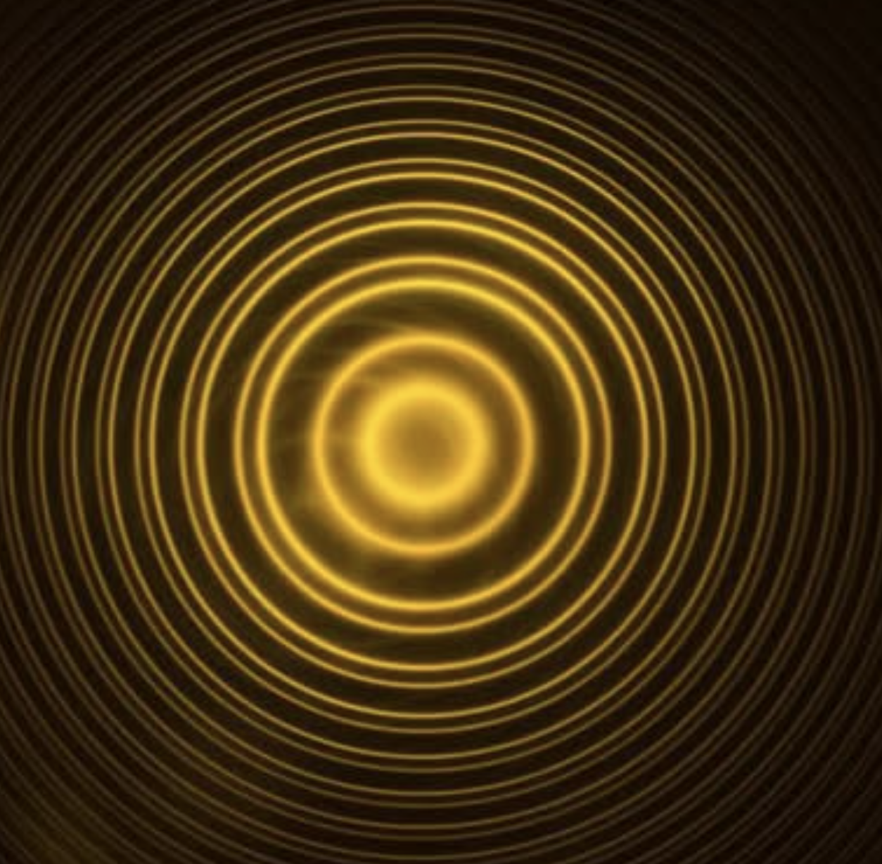
A famous high resolution use of Fabry-Perot took place in the separation of sodium yellow doublet of wavelengths \(588.9950\text{ nm}\) and \(589.5924\text{ nm}\text{.}\) You can see an image shown in Figure 47.33 of the separation of sodium doublet. The two sodium D-lines are repeated for different orders. Picture Credit: https://www.instagram.com/gld.munoz/p/CjGifsuK7Ew/?img_index=1.
An instrument used for resolving spectral lines is rated by its resolving power. It is proportional to the inverse of minimum separation in wavelengths \(\Delta\lambda_\text{min}\) that the instrument can resolve .
\begin{equation*}
\text{Resolving Power } \propto\ \frac{1}{\Delta\lambda_\text{min}}.
\end{equation*}
To make resolving power a dimensionless quantity, we multiply the right side by average wavelength. Thus,
\begin{equation}
\text{Resolving Power } =\left| \frac{\lambda_\text{av}}{\Delta\lambda_\text{min}}\right|.\tag{47.50}
\end{equation}
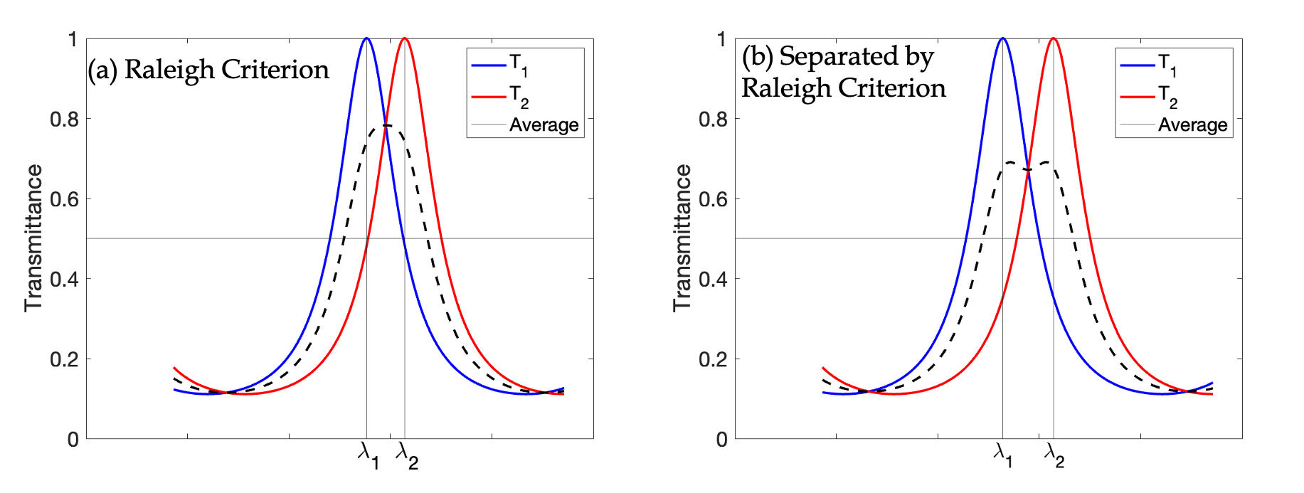
How do we tell if two nearby wavelengths are separated? This is the same type of question as we had when we were studying telescopes. There, the question was how to tell if we could tell whether there were two stars or one star on the CCD. A commonly used criteria, called Raleigh criterion is that if the maximum of peak of one will be at less than half-width from the other peak, then we cannot be sure there are two peaks.
Suppose, we have a light that is mixture of two wavelengths \(\lambda_1\) and \(\lambda_2 \gt \lambda_1\text{.}\) When this light is sent through a Fabry-Perot, they form peaks at \(\lambda_1\) and \(\lambda_2\) with half-width at half maximum of each to be \(w_1\) and \(w_2\) respectively. Raleigh criterion says that to be resolvable, we must have
If \(w_2 \ge w_1\text{,}\) then, we just need to check \(\lambda_1 \lt \lambda_2 - w_2\text{.}\)Figure 47.34(a) illustrates the idea behind what we would consider barely separated by Raleigh criterion. Figure (b) is visibly separated as you can see the dip between the peaks.
We can use Eq. (47.48) to cast the resolving power in terms of finesse coefficient \(F\) of the instrument. For nearly normal incidence, resolving power can be shown to be
\begin{equation}
\text{Resolving Power } = \left|\frac{\lambda_\text{av}}{\Delta\lambda_\text{min}} \right| = \left[\frac{\pi \sqrt{F}}{2}\right]\, \frac{2 n d}{\lambda_\text{av}},\tag{47.51}
\end{equation}
where the quantity between brackets, viz. \(\pi \sqrt{F}/2 \text{,}\) is called finesse of the instrument. We will denote finesse by \({\cal{F}}\text{.}\)
where I have omitted subscripts for simplicity. You can use this formula to find \({\cal{F}}\) you need for the resolution of light required, which can then be used to find the minimum reflectance needed on the cavity mirrors.
In the next chapter you will study another device called the diffraction gratings which are also used for the separation of light of different wavelengths. It turns out that it is much harder to construct a diffraction grating with as high a resolving power as a Fabry-Perot interferometer. For instance, let \(n = 1\text{,}\)\(d = 1\text{ cm}\text{,}\)\(\lambda = 650\text{ nm}\text{,}\) and reflectance \(R = 0.98\text{,}\) then the resolving power would be \(4.8 \times 10^6\text{.}\) To get this kind of resolving power from a diffraction grating (which will be discussed in the next chapter) that has slit separation of \(1000\text{ nm}\text{,}\) you will need diffraction from \(1,560,000\text{ slits}\text{,}\) or \(1.56\)-meter wide diffraction grating!
Show that the path difference between two successively transmitted waves in the Fabry-Perot interferometer is given by \(2d\cos\theta\text{,}\) where \(d\) is the distance between the mirrors.
2.Resolving Power Required in a Fabry Perot Instrument for Separating Sodium Yellow Doublet.
Sodium yellow doublet consists of wavlengths \(0.5889950\,\mu\text{m}\) and \(0.5895924\,\mu\text{m}\text{.}\) These lines are to be separated by a Fabry-Perot interferometer that has air as its medium and length of cavity is \(1.0\text{ cm}\text{.}\) What is the minimum resolving power and finesse of a Fabry-Perot interferometer used to resolve these lines?
Hydrogen atom has two red lights in its spectrum of wavelengths \(656.272\, \text{nm}\) and \(656.2852\, \text{nm}\text{.}\) Figure out the parameters of a Fabry-Perot interferometer that you would need if you are to resolve the two wavelengths successfully.
4.Minimum Wavelength Difference Resolvable in a Fabry-Perot Interferometer.
You have acquired a Fabry-Perot interferometer with the following specifications: \(d=2.0\text{ cm}\text{,}\)\(R=0.9\text{,}\)\(n=1.1\text{.}\) Find the minimum wavelength difference you can resolve near wavelength of \(\lambda=0.632\ \mu\text{m}\text{.}\)
Recall that peaks of \(T\) occur at \(\Delta_{12}=2\pi m\) with \(m\) an integer. Let \(\Delta_{12}\) at half height around peak \(\Delta_{12}=2m\pi\) for some \(m\) be
\begin{equation*}
\Delta_{12} = 2\pi m \pm \frac{w}{2},
\end{equation*}
where \(w\) is the full width. Setting \(T\) at these values to \(1/2\) we get the following condition.
\begin{equation*}
\frac{1}{2} = \frac{1}{1+ F\sin^2\left(\pi m \pm \frac{w}{4} \right)}.
\end{equation*}
Rearraning we get
\begin{equation*}
1+ F\sin^2\left(\pi m \pm \frac{w}{4} \right) = 2.
\end{equation*}
Now, we use cosine double angle formula and expanding the resulting cosine to change this to
6.Reflectivity of Mirrors of Fabry-Perot Cavity Required to Separate Mercury Yellow-Orange Doublet.
What should be the reflectivity of the Fabry-Perot etalon so that the yellow-orange doublet of mercury, which correspond to wavelengths \(576.959\text{ nm}\) and \(579.065\text{ nm}\text{,}\) are just resolvable by Raleight criterion in \(m=100\) order?
The resolving of two wavelengths will occur if the peaks of constructive interference corresponding to the two wavelengths fall outside of half-width of the peaks. This give the condition of resolution in the \(m^\text{th}\) order to be