The simplest capacitor consists of two conductors. The two conductors are called plates of the capacitor regardless of their shape. Moving charges from one plate to the other creates a situation where one plate is positively charged and the other negatively charged. Work done in doing so is stored as the electrical energy in the capacitor.
Early versions of capacitors were invented by the Dutch physicist Pieter van Musschenbroek of the University of Leiden around 1746, and are called Leiden jars.
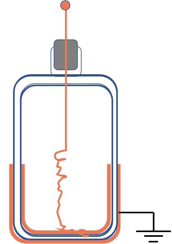
A Leiden jar shown in Figure 32.30 consists of a glass jar with inner and outer metal coatings. The inner coating is in contact with a brass rod through a loose metal chain. The brass rod passes through a cork stopper and a metal knob is mounted on the rod.
When you place some electric charges on the knob of a Leyden jar, they spreads to the inner metal which attracts opposite charges of the outer metal. By grounding the outer surface of the outer metal, you transfer the charges on the outer surface of the outer metal to the ground and you are left with only opposite charges on the inner metal and the inner surface of the outer metal.
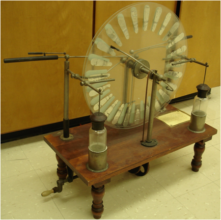
Leiden jars were instrumental in early experiments on electricity. Figure 32.31 shows a pair of Leiden jars used in a Wilmhurst mill for storing charges. Leiden jars can be charged to fairly high voltages, e.g., in a Wilmhurst mill. When wires connecting the two plates of a charged Leiden jar are brought near each other spectacular sparks from one wire to the other are often visible. Leiden jars are sometimes also called condensers.
Figure32.31.Wilmhurst mill uses Leiden jars, the two bottle-shaped containers in the figure, to store separated charges by rubbing off rotating metal strips. The wheel contains strips of metal that rubs against a metal wool when the wheel rotates. The separated charges are sent to Leyden jars for storage.
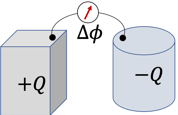
Consider two arbitrarily shaped conductors that have equal and opposite charges \(+Q\) and \(-Q\) with a potential difference of \(\Delta \phi\) on them as shown in Figure 32.32. Independently of the shape, size, or separation of the two conductors, voltage between the plates will increase if we put more charges on the two.
The proportionality constant \(C\) is called capacitance. The capacitance refers to the capacity of a capacitor for charges. A capacitor with higher capacitance will hold more charge for the same potential difference than the one with a smaller capacitance.
It turns out that 1 Farad is too big a unit for laboratory use. Usually one uses micro-farad (\(\mu\text{F}\)) or pico-farad (\(\text{pF}\)) in the lab.
You can also define the capacitance of a single isolated conductor if you send its partner to infinity. For instance, an isolated sphere of radius \(R\) with charge \(Q\) has the following potential \(\Delta \phi\) with respect to infinity.
\begin{equation*}
\Delta \phi = \frac{Q}{4\pi\epsilon_0 R }.
\end{equation*}
Comparing this to Eq. (32.6), we see that the capacitance \(C_{\text{sphere}}\) sphere of a single metallic sphere would be given by the following formula.
\begin{equation*}
C_{\text{sphere}}= 4\pi\epsilon_0 R\ \ \text{(the other partner at infinity)}
\end{equation*}
Charging a capacitor from neutral plates to charged plates is usually accomplished by moving eletrons from positive plate to the negative plate, which is the opposite of the electrical force on the electron. That means, you will need to do work to charge a capacitor.
Below, we will show that the energy required to charge a capacitor from neutral to a final charge \(\pm Q_f\) with final potential difference between plates \(V_f\) is given by
\begin{equation}
U = \frac{1}{2}\ Q_f V_f.\tag{32.7}
\end{equation}
This is the amount of electrostatic energy stored in the capacitor. We can write this in couple of other forms by using the capacitor formula, \(Q=CV\text{.}\)
\begin{equation}
U = \frac{1}{2}\ C V_f^2 = \frac{1}{2}\frac{Q_f^2}{C}.\tag{32.8}
\end{equation}
Subsection32.5.2(Calculus) Energy Stored in a Charged Capacitor
Say, you have two neutral plates. How would you make a charged capacitor from them? You would simple move electrons from one plate, say A, to the other, say B. As a result A will become positively charged and B negatively charged. Work done by you will be stored as electrical energy in the capacitor.
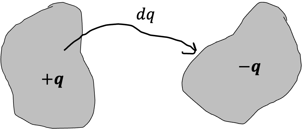
To get a concrete formula for energy stored in a charged capacitor, let us work with plates that are initially neutral. At some stage, positive plate will have charge \(+q\) and negative plate with charge \(-q\) as shown in Figure 32.33. Let, at this stage, positive difference between the plates be \(V\text{.}\) The capacitor equation, Eq. (32.6) tells us that, charges and potential difference before transfer of any more charges is
Now, we move an infinitesimal charge \(dq\) from the negative plate and place it on the positive plate, thus increasing the charges on each plate. The charge \(dq\) underwent a potential difference of \(V\text{.}\) Therefore, energy of the capacitor changes by this amount.
\begin{equation*}
dU = \frac{1}{C}\, q dq.
\end{equation*}
Integrating from \(q=0\text{,}\) to final charge value, \(q=Q_f\text{,}\) gives energy required to charge the capacitor from neutral to \(Q_f\text{.}\)
\begin{equation}
U = \frac{1}{C}\, \int_0^{Q_f}q\, dq = \frac{1}{2}\frac{1}{C}Q_f^2.\tag{32.10}
\end{equation}
Let potential difference between plates with this final charges be \(V_f\text{.}\) The capacitor equation tells us that
\begin{equation*}
Q_f = C V_f.
\end{equation*}
We can use this to write energy of a charged capcitor in other forms as we have seen above.
\begin{equation}
U = \frac{1}{2}\frac{1}{C} Q_f^2= \frac{1}{2}\ C V_f^2 = \frac{1}{2}\ Q_f V_f.\tag{32.11}
\end{equation}
Example32.34.Capacitance of a Metal Screw and Nut Capacitor.
A steel screw and a steel nut fixed to a dry wooden board at a distance of \(1.0\text{ cm}\) from each other are connected to a \(12\text{ V}\) battery. When they are fully charged, the screw has a charge of \(+10\text{ pC}\) and the nut a charge of \(-10\text{ pC}\text{.}\) What is the capacitance of the screw/nut capacitor?
We use the fundamental capacitor formula \(Q = C\Delta \phi\) with \(\Delta \phi = 12\text{ V}\) provided by the battery. This gives the following for the capacitance.
Example32.35.Charges on two Concentric Spherical Metals Connected by a Battery.
Two concentric spherical metal shells separated by nonconducting air have a capacitance of \(300\text{ pF}\text{.}\) What are the charges on the two shells when the potential difference between them is \(1.5\text{ V}\text{?}\)