   
Logo image

Physics Bootcamp

Section 18.8 Dynamic Fluid Bootcamp

Exercises Exercises

Fluid Flow

1. Volume and Mass Flow Rates in a Cylindrical Pipe.
Follow the link: Example 18.2.
2. Varying Flow Speeds in a Garden Hose and Nozzle.
Follow the link: Example 18.3.
4. Flow in a Branching System - The Human Circulatory System.
Follow the link: Exercise 18.1.5.2.

Bernoulli’s Equation

5. Pumping Water in a Tall Building.
Follow the link: Example 18.5.
7. Draining a Tank by Using a Pipe that Varies in Cross Section and Height.
Follow the link: Exercise 18.2.1.
8. Speed of Water when Pumping Water to the Tenth Floor of a Tall Building.
Follow the link: Exercise 18.2.2.
9. Atmospheric Pressure Suporting Enclosed Water Tank from Leaking.
Follow the link: Exercise 18.2.3.

Applications of Bernoulli’s Equation

10. Example of Lift Force on Airplane Wing.
Follow the link: Example 18.14.
12. The Lift Force on an Airplane Wing.
Follow the link: Example 18.18.
15. Speed of Flow of Water in a Pipe Determined by a Venturi Meter.
Follow the link: Exercise 18.3.4.2.

Viscosity

16. Sliding Microscopic Slides with Liquid Between Them.
Follow the link: Example 18.26.

Stoke’s Law

17. The Steady Speed of Fall of a Steel Ball in Glycerin.
Follow the link: Example 18.27.
18. Time to Reach Teminal Speed in a Viscous Fluid.
Follow the link: Example 18.28.

Poiseuilli’s Law

19. Determining Diameter of Vein from Pressure Difference and Length of Vein.
Follow the link: Example 18.29.
21. A Medical Application of Poiseuilli’s Law in Quantifying Blood Flow Blockage.
Follow the link: Exercise 18.6.3.2.

Turbelence

22. Reynolds Number of Water and Turbulent Flow.
Follow the link: Exercise 18.7.1.
23. Determining if a Flow is Turbulent.
Follow the link: Example 18.31.
24. Volume Rate of Flow for a Given Reynold Number.
Follow the link: Exercise 18.7.2.

Miscellaneous

25. Pressure at Tap in a Tank of Water.
A filled large water tank has a pipe of cross-sectional area \(1.2\, \text{cm}^2\) attached at a depth \(30\, \text{cm}\) from the top. There is a valve controlling the flow of water through the pipe. Find the pressure at a point B in the pipe as shown in Figure 18.32, (a) when no water is flowing, and, (b) when water is flowing steadily.
Figure 18.32.
Answer.
(a) \(1.042 \times 10^5\ \text{Pa}\text{;}\) (b) \(1.013 \times 10^5\ \text{Pa}\text{.}\)
Solution 1. a
No flow means that we have fluid statics. In this case, we will set \(v=0\) in the Bernoulli’s equation for the point B and a point at the top layer of the water. This calculation gives
\begin{equation*} p_B = p_{\textrm{atm}} + \rho g h = p_{\textrm{atm}} + 2,940\ \textrm{Pa}. \end{equation*}
Solution 2. b
When the valve is open, the pressure at B will be based on the flow against the atmospheric pressure. When you use the Bernoulli’s equation between the point B and a point at the tip of the freely flowing opened tube you would obtain
\begin{equation*} p_B = p_{\textrm{atm}}. \end{equation*}
26. Narrowing of Water Faucet Flow.
As water falls from a faucet it narrows. What will be the diameter and the area of the cross-section of flow \(10\text{ cm}\) from the exit of a water faucet that has an opening of \(2\text{ cm}\) diameter if volume rate of flow of water is \(0.25\text{ L/s}\text{?}\)
Hint.
The pressure at the top point and bottom point are equal to atmospheric pressure.
Answer.
\(1.55\text{ cm}^2\text{,}\) \(1.4\text{ cm}\text{.}\)
Solution.
Label point at the bottom by 1 and the top by 2. Since the flow occurs freely against air the pressures at the two points in the question are equal to the atmospheric pressure.
\begin{equation*} p_1 = p_2 = p_\text{atm}. \end{equation*}
We get the following from Bernoulli’s principle.
\begin{equation} \dfrac{1}{2} v_1^2 = \dfrac{1}{2} v_2^2 + g h. \tag{18.43} \end{equation}
This equation can be transformed using the conservation of volume (\(A_1 v_1 = A_2 v_2\)) so that we can find \(A_1\) at the point 1 from the given data. Let us denote the volume rate of flow by the letter \(c\text{.}\) Then we have
\begin{equation*} A_1 v_1 = A_2 v_2 = c. \end{equation*}
Therefore
\begin{equation*} v_1 = \dfrac{c}{A_1},\ \ v_2 = \dfrac{c}{A_2}. \end{equation*}
Now we put these in Eq. (18.43) and solve for \(A_1\text{.}\)
\begin{equation} A_1 = \left[ \dfrac{1}{A_2^2} + \dfrac{2 g h}{c^2} \right]^{-1/2}.\tag{18.44} \end{equation}
Let \(d_2\) be the diameter at the top point. The given values are
\begin{align*} A_2 \amp = \dfrac{\pi}{4} d_2^2 = \pi\text{ cm}^2.\\ h \amp = 10\ \text{cm}\\ g \amp = 981\ \text{cm/s}^2\\ c \amp = 0.25\ \text{L/s} = 0.25\times 10^{-3}\ \text{m}^3/\text{s} \\ \amp = 0.25\times 10^{3}\ \text{cm}^3/\text{s}. \end{align*}
Putting these numbers in the formula for \(A_1\) we find that \(A_1 = 1.55\text{ cm}^2\text{.}\) The diameter of water column at that point would be \(d_1 = \sqrt{4 A_1/\pi } = 1.4\text{ cm}\text{.}\)
27. Critical Height of a Siphon.
A siphon is an ingenious device for removing fluid from a container that must not be tipped. In a siphon, you fill a U-tube or a flexible pipe with a liquid, close both ends, invert the pipe and place the higher end in the liquid and the other end in another container. Now, when you open the ends, you find that fluid starts to drain out as long as the highest point Q of the pipe is not too high.
Find the maximum height \(h\) so that water can drain when the open end in the water is at a depth of \(d\) and the other end \(R\) of the siphon is a height \(b\) below. Denote the density of the fluid by \(\rho\) and give your answer in terms of \(p_{atm}\text{,}\) \(\rho\text{,}\) \(g\text{,}\) \(d\) and \(b\text{.}\)
Check answer: if \(\rho = 13.5\text{ g/cc}\text{,}\) \(d = 10\text{cm}\text{,}\) and \(b = 20\text{ cm}\text{,}\) then \(h\lt 46\text{ cm}\text{.}\)
Hint.
At the critical height the flow will stop!
Answer.
\(h_c = \dfrac{p_{\text{atm}}}{\rho g }.\)
Solution.
At the critical height the flow will stop. Let this value of \(h\) be denoted by \(h_c\text{.}\) The atmospheric pressure at the tank is balanced by the water column on the left end of the siphon. That is
\begin{equation*} p_{\text{atm}} = \rho g h_c. \end{equation*}
Therefore, the critical \(h_c\) is
\begin{equation*} h_c = \dfrac{p_{\text{atm}}}{\rho g }. \end{equation*}
28. (Calculus) Time to Empty a Tank Using a Siphon.
Consider the siphon shown. If the area of cross-section of the container is \(A_0\text{,}\) the volume of water in the container is \(V\text{,}\) and area of cross-section of the pipe is \(A\text{,}\) how long will it take to empty the container? Do not assume the speed of flow inside the container to be zero.
Answer check: For \(A = 1\text{ cm}^2\text{,}\) \(A_0 = 1\text{ m}^2\text{,}\) \(V = 10^{-2}\text{ m}^3\text{,}\) and \(b = 1\text{ m}\text{,}\) \(t = 5.6\text{ sec}\text{.}\)
Hint.
Set up Bernoulli’s equation with velocity in the tank written as \(dy/dt\text{.}\)
Answer.
\(T = \sqrt{\dfrac{2}{g}} \left( \sqrt{b+d} - \sqrt{b}\right)\sqrt{a^2-1}.\)
Solution.
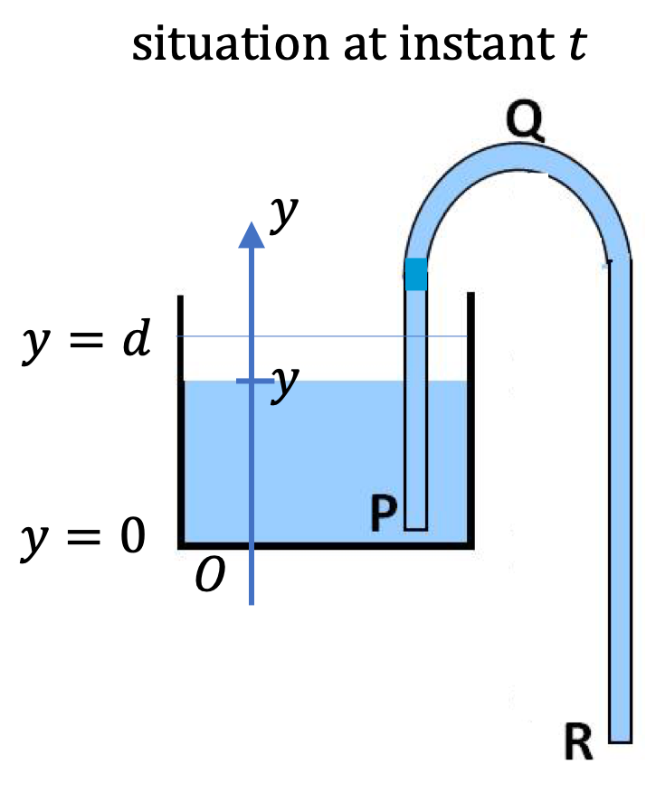
To minitor the progress of emptying of the tank, we use a \(y\)-coordinate of the top of the water at instant \(t\) with initial value \(y=0\text{.}\) This gives the velocity at the top, to be denoted by \(v\text{,}\) which is a function of time \(t\text{.}\)
\begin{equation*} v = -\dfrac{dy}{dt}, \end{equation*}
where minus is because the layer is moving down while positive \(y\) axis is pointed up.
The Bernouli equation for the flow through the entire siphon will be
\begin{equation} p_{\text{atm}} + \dfrac{1}{2} \rho v^2 + \rho g (b + y) = p_{\text{atm}} + \dfrac{1}{2} \rho v_R^2. \tag{18.45} \end{equation}
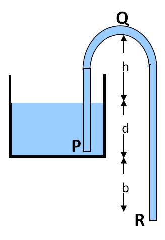
Let \(v_R\) denote the speed with which fluid comes out at bottom. The conservation of volume gives
\begin{equation*} A_0 v = A v_R. \end{equation*}
Putting this in the Eq. (18.45) yields
\begin{equation*} v = \sqrt{\dfrac{2g(b+y)}{a^2-1}},\ \ \ (a \ne 1) \end{equation*}
where \(a = A_0/A\text{.}\) Replacing \(v\) by \(-dy/dt\) this eqution becomes a differential equation.
\begin{equation*} -\dfrac{dy}{dt}= \sqrt{\dfrac{2g(b+y)}{a^2-1}}, \end{equation*}
We can write this in a way that allows integrating easier.
\begin{equation} \dfrac{dy}{ \sqrt{ b + y} } = - \sqrt{\dfrac{2g }{a^2-1}} dt.\tag{18.46} \end{equation}
Integrating this equation from \(y=d\) to \(y=0\) corresponding to \(t=0\) to \(t=T\text{,}\) the time to drain gives us the following result.
\begin{equation*} 2\sqrt{b+d} - 2\sqrt{b} = \left[ \sqrt{\dfrac{2g }{a^2-1}}\right]\ T. \end{equation*}
Therefore,
\begin{equation*} T = \dfrac{\sqrt{2}}{\sqrt{g}}\sqrt{ a^2-1 } \left( \sqrt{b+d} - \sqrt{b}\right). \end{equation*}
29. Viscometer.
A viscometer is a device that measures viscosity of a liquid. In a common viscometer the liquid is put between two drums, one of which is fixed and the other rotated at a constant angular speed. The torque needed to rotate the drum is related to the viscosity.
In a particular viscometer the inner drum is rotated at \(50\text{ rev/min}\text{.}\) The outer diameter of the inner drum is \(5\text{ cm}\) and the inner diameter of the outer fixed drum is \(6\text{ cm}\text{.}\) The height of the drums is \(4\text{ cm}\text{.}\) If the torque on the inner drum is measured to be \(9.75 \times 10^{-4}\text{ N.m}\text{,}\) what is the viscosity of the fluid?
Hint.
No hint
Answer.
\(\tau =4\pi \eta \omega H \dfrac{R_1^2 R_2^2 }{R_2^2 - R_1^2},\)
Solution.
I will leave this problem for you to attempt and discuss. The calculation will go similar to the calculation leading up to the Poseuille’s law derived in the book. The calculation here will be related to the torque due to the viscous force between \(r\) and \(r + \Delta r\) layers of length L and width \(2\pi r\text{.}\) You can express the torques in terms of the drag force and also in terms of the pressure in the fluid. You will enjoy this problem if you are comfortable using Cylindrical coordinates.
The answer for torque on the outer cylinder when the internal cylinder is fixed is
\begin{equation*} \tau =4\pi \eta \omega H \dfrac{R_1^2 R_2^2 }{R_2^2 - R_1^2}, \end{equation*}
where \(\omega\) is the angular frequency of rotation, H is the height of the cylinders, and \(R_1\) and \(R_2\) the radii of the two cylinders.