   
Logo image

Physics Bootcamp

Section 44.6 Image Formation by Thin Lens

A converging lens can form a real as well as a virtual image, but a diverging lens can form only a virtual image. To find the image of an object we select representative points on the object and find the image of each point by tracing rays from that point. We will study objects that have the shape of a simple arrow so that we can also study the lateral magnification of the object. In this section, we will study image formation by the ray tracing method, i.e., by drawing rays rather than using lens equation.

Subsection 44.6.1 Real Image by a Convex Lens

Real image of a point light source is formed if physical rays actually meet after passing through the lens. For a convex lens this happens if object is placed at a distance further than the first focal point of the lens. Figure 44.52 shows the setup we will use to illustrate the method of finding location, size, and orientation of the real image. The object is the arrow OP.
As usual we start with drawing the lens, the center plane of the lens, and the symmetry axis. Then we position the foci \(\text{F}_1\) and \(\text{F}_2\) symmetrically about the lens, and place the object at the object OP distance from the center plane of the lens. It is a good idea to keep the height of the object smaller then the height of the lens. It is also best to draw the object from the axis rather than straddling the axis. Label appropriate points of the object.
Figure 44.52. Real image by a converging lens by ray tracing method. Object is OP and image is IQ. Rays \(11'\) and \(22'\) were drawn to locate the image Q of point P. The image I of point O is deduced by symmetry. The other rays illustrate that any other ray from P that strikes the lens will emerge in the direction of image point Q. Since real rays cross there and continue to move on, you need a screen to view the image.
In this example only the ends points O and P need labeling. We will work out the image of point P and by symmetry the image point of O will be on the axis in the plane containing the image point of P. To aid the drawing of rays, we draw a vertical line at the center of lens and all changing in ray directions are drawn fron this central line of the len.
Steps in the Drawing: Any two rays from P and striking the lens will work, but since we know the behavior of three special rays discussed in Subsection 44.5.1, we will choose two of them. The simplest one is the chief ray, labeled \(11'\) from P that passes through the lens undeviated. Next is a ray, labeled \(22'\) that will be incident on the lens parallel to the axis and pass through the second focal point \(\text{F}_2\text{.}\) These rays cross at point Q, which is the image of point P.
Now, if you draw the third special ray, e.g., \(33'\text{,}\) which passes through the first focal point before being incident on the lens, this ray will also pass through point Q. As a matter of fact, any arbitrary ray starting at P that goes through the lens will end up passing through Q.
Note that, even though we did not need to draw ray \(33'\) to locate the image point Q, it is wise to draw this ray just to make sure other rays were drawn correctly. So, you should develop the habit of drawing all three special rays!

Subsection 44.6.2 Virtual Image by a Convex Lens

If an object is withing a focal length of a convex lens, no image will form on any screen on the other side of the lens like we saw in Figure 44.52. When rays from the object emergy from the lens, they diverge as shown in Figure 44.53. When you are looking through the lens, the rays that started from P will appear to to come from point Q. This is virtual image of point P.
Figure 44.53. Virtual image by a converging lens by ray tracing method. Object is OP and image is IQ. Rays \(11'\) and \(22'\) were drawn to locate the image Q of point P by extending the transmitted rays backwards. The image I of point O is deduced by symmetry. The other rays illustrate that any other ray from P that strikes the lens will emerge in the direction from image point Q. Since real rays do not cross at the image, you cannot place this image on any screen. You can only look at it when viewing through the lens.
Steps in the Drawing: As before, any two rays from P and striking the lens will work. The simplest one is the chief ray, labeled \(11'\) from P that passes through the lens undeviated. Next is a ray, labeled \(22'\) that will be incident on the lens parallel to the axis and pass through the second focal point \(\text{F}_2\text{.}\) The emerging rays \(1'\) and \(2'\) are diverging away from each other. So, we draw their extensions backwards as shown by dashed lines. They meet at Q, which is the virtualimage of point P of the object.
Now, if you draw the third special ray, e.g., \(33'\text{,}\) which passes through the first focal point before being incident on the lens, this ray will emerge in a direction that will seem like it is cming from Q. As a matter of fact, any arbitrary ray, such as \(44'\) from P will appear to be coming from Q.
Since transmitted physical rays are not meeting at Q, this image cannot be placed on a screen. If you placed at screen at location of IQ, there will be no image. The screen will just have direct illumination from object OP. When you look through the lens, what you see is the image IQ and not the object OP.

Subsection 44.6.3 Image by a Concave Lens

Image by a concave lens is always virtual. That means you can look at the image when you view and object through the lens, but you cannot place the object on any screen. Ray tracing works same way here as it does for the virtual image in a cnvex lens shown in Figure 44.53. As shown in Figure 44.54, we draw two rays from a point on the object to locate its image by extension of the transmitted rays.
Figure 44.54. Virtual image by a diverging lens by ray tracing method. Object is OP and image is IQ. Rays \(11'\) and \(22'\) were drawn to locate the image Q of point P by extending the transmitted rays \(1'\) and \(2'\) backwards. The image I of point O is deduced by symmetry. Since real rays do not cross at the image, you cannot place this image on any screen. You can only look at it when viewing through the lens.

Exercises 44.6.4 Exercises

1. Ray Tracing Through a Convex Lens.

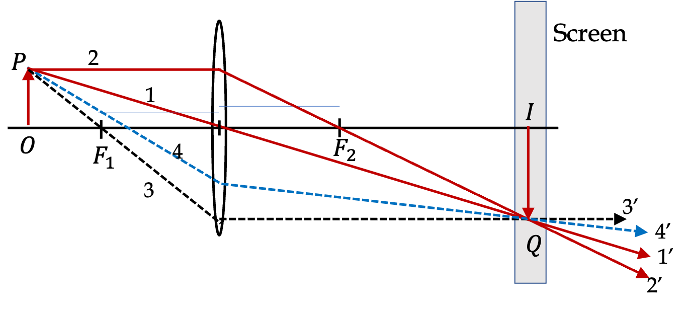
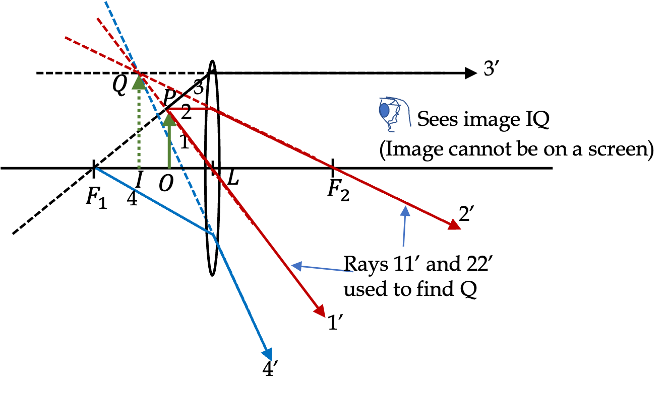
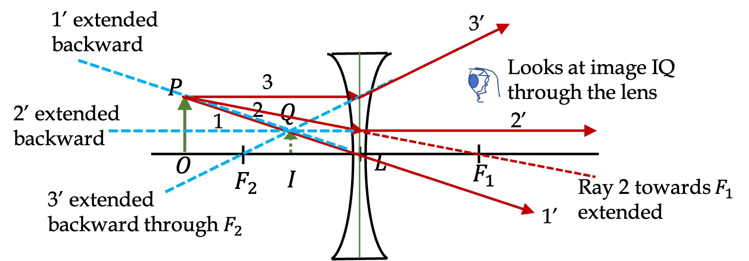
(a) Draw rays to form an image of an object OP vertically on the axis in front of a converging lens placed outside the focal length. (b) Use plane geometry in you figure and prove the following relation.
\begin{equation*} m \equiv \frac{h_i}{h_o} = -\frac{q}{p}. \end{equation*}
Solution 1. a
The rays for image formation are shown in Figure 44.55.
Figure 44.55.
Solution 2. b
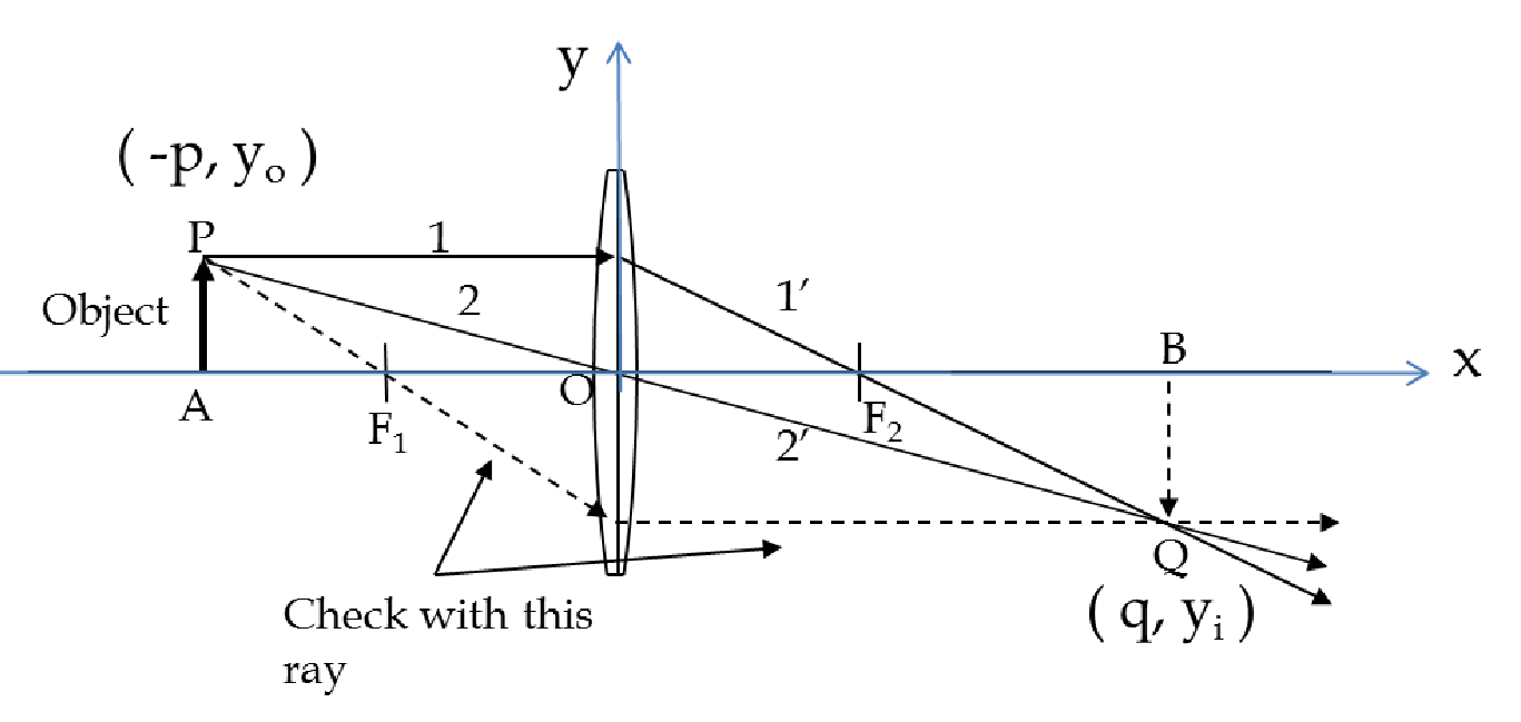
You can use plane geometry or analytically geometry to solve this problem. I will illustrate the analytical geometry here. To solve by plane geometry look for similar triangles in the figure. For analytical procedure we will use the \(x\) and \(y\) axes as shown and denote the heights of the object and the image by their \(y\)-coordinates. Now, we can equate the slope of the line POQ by using the coordinates of P and O and the coordinates of O and Q. This gives
\begin{equation*} -\dfrac{y_0}{p} = \dfrac{y_i}{q},\ \ \Longrightarrow\ \ \dfrac{y_i}{y_0} = - \dfrac{q}{p}. \end{equation*}