Logo image

Physics Bootcamp

Section 34.11 Capacitor Discharging Circuit

When an uncharged capacitor is connected to a voltage source, electrons flow from the negative terminal of the voltage source to the one of the plates of the capacitor which repels electrons on the other plate causing a flow of electron from the other plate to the positive terminal of the voltage source. Consequently, two plates of the capacitor develop equal charges of opposite types.
At any instant the amount of charge on any one of the plates \(Q(t)\) is related to the voltage \(V(t)\) across the plates at that instant by the usual capacitor formula.
\begin{equation*} |Q(t)| = C\,|V(t)| \end{equation*}
Once the capacitor is fully charged, the current in the branch of the circuit that has the capacitor stops and the voltage across the capacitor is the maximum voltage the capacitor can have since its would have the maximum charge allowed on the plates.
A charged capacitor provides a ready supply of separated charges. When you provide a conducting path for excess electrons on the negative plate to drift to positive plate, it leads to discharge of the capacitor. This process releases electrical energy in a short time.
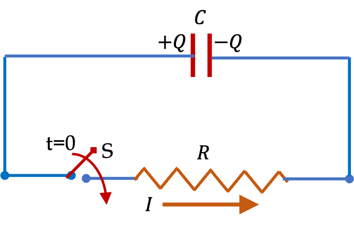
To use charges on a charged capacitor one can connect the ends of the capacitor through a device of resistance \(R\) and a switch S as indicated in Figure 34.72. When the switch is closed, current flows in the circuit until electrons from the negative plate neutralize the positive charges on the positive plate.
Figure 34.72. A simple capacitor discharging circuit.
Rate of discharge depends on the current value of charges on the plates, which leads to charge decaying exponentially. Let \(Q_0\) be the starting charge at \(t=0\text{.}\) Then, using Calculus, it will be shown below that charge remaining on capacitor at time \(t\) will be
\begin{equation*} Q(t) = Q_0 e^{ - t/RC}. \end{equation*}
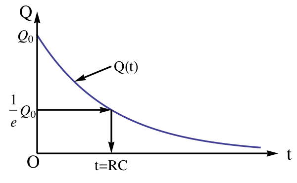
A plot of this function versus time is shown in Figure 34.75. The rate of discharge, i.e., current in the circuit varies with time and is proportional to the charge on the plates at the instant.
\begin{equation*} \text{Rate of discharge } = \frac{1}{R\,C}\, Q(t). \end{equation*}
The time to reach \(\frac{1}{e}\) of the original charge, where \(e \) is the Euler number with value \(e = 2.718...\text{,}\) is an important characteristic of the circuit. This time is called time constant of the circuit. The time constant is usually denoted by the Greek letter \(\tau\text{.}\) Of course, during this time, \(1-1/e\) of the charge, which is approximately two-thirds of the charge, has been discharged through the circuit. The time constant of the circuit in Figure 34.72 is product of the resistance and capacitance of the circuit.
\begin{equation} \tau = R\,C.\tag{34.49} \end{equation}
By adjusting \(R\) we can congtrol the rate at which dischsrging of a capacitor can take place. In another section, we will study charging process. We will find there that the rate of charging has also the same time constant.

Example 34.73. Time Constant of an RC-Circuit.

Determine the time constant of a circuit that has a 30 \(\mu\)F capacitor in series with a 200 \(\Omega\) resistor.
Answer.
\(6\, \text{ms}\text{.}\)
Solution.
For this circuit, the time constant is given by \(RC\text{.}\)
\begin{equation*} \tau = RC = 200\:\Omega\times 30\:\mu\textrm{F} = 6000\:\mu\textrm{s} = 6\:\textrm{ms}. \end{equation*}

Subsection 34.11.1 (Calculus) Equation of Motion for Discharging a Capacitor

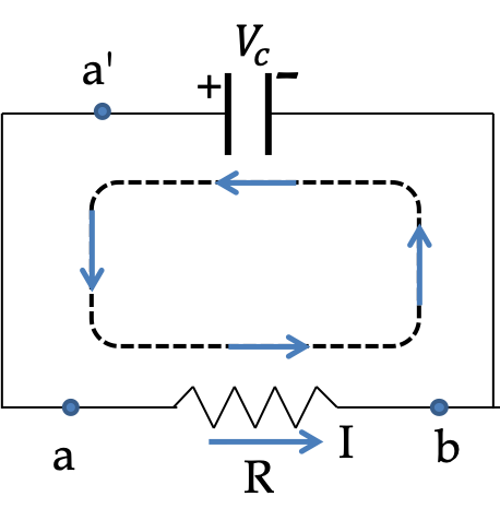
Let us examine discharging circuit in Figure 34.72 at instant \(t\text{.}\) Let \(I(t)\) be current in the circuit, \(\pm Q(t)\) be charges on the plates. The potential drop \(V_c \) across the capacitor is given by the capacitor equation.
\begin{equation} V_c(t) = \frac{Q(t)}{C}.\tag{34.50} \end{equation}
By Kirchhoff’s Loop Rule on the loop a-b-a’ in Figure 34.74, we find the following equation for relation among these quantities.
\begin{equation} -R I + V_c = 0.\tag{34.51} \end{equation}
Current \(I\) is rate at which charge is decreasing in time. Therefore,
\begin{equation} I = - \frac{dQ}{dt}.\tag{34.52} \end{equation}
Figure 34.74.
From Eqs. (34.50) to (34.52) gives the following equations for rate at which charge drops in time.
\begin{equation} \frac{dQ}{dt} = - \frac{1}{RC}\, Q.\tag{34.53} \end{equation}
Let \(\pm Q_0\) be the charges on capcitor plates at \(t=0\text{,}\) when the circuit switch was closed. Then, Eq. (34.53) can be solved to show that charge at an arbitrary instant \(t \gt 0\) will be
\begin{equation} Q(t) = Q_0\, e^{- t / RC}.\tag{34.54} \end{equation}
A plot of \(Q\) versus \(t\) presented in Figure 34.75 shows the exponential decaying behavior of the discharge process.
Figure 34.75. Charge on positive plate decays exponentially with time with a time constant \(\tau= RC\text{.}\) The time constant is equal to the time for charge to decay to \(1/e\) of its initial value.
Plots of current \(I\) vs \(t\) and potential drop across the capacitor \(V_c\) vs \(t\) show similar plots.
\begin{align*} I \amp = -\frac{dQ}{dt} = \frac{Q_0}{RC}\, e^{- t / RC}.\\ V_c \amp = \frac{Q}{C} = \frac{Q_0}{C}\, e^{- t / RC}. \end{align*}

Example 34.76. Numerical Example of Discharging a Capacitor.

Consider a capacitor of capacitance \(2\;\mu\text{F}\text{.}\) (a) Find the time constant of a circuit when the capacitor is connected to a \(1.0\text{ k}\Omega\) resistor. (b) Suppose the capacitor was charged to contain \(5.0\;\mu\text{C}\) at \(t = 0\text{.}\) At what time will there be \(2.0\;\mu\text{C}\) left on the capacitor?
Answer.
(a) \(2\text{ ms} \text{,}\) (b) \(1.8\text{ ms} \text{.}\)
Solution 1. (a)
The time constant follows from the result \(\tau = RC\) for this circuit given above.
\begin{equation*} \tau = RC = 1000\ \Omega\times 2\times 10^{-6}\text{ F} = 2\times 10^{-3}\text{ sec} = 2\text{ ms}. \end{equation*}
Solution 2. (b)
Using (34.54), we set up the following equation for charge at an unknown time.
\begin{equation*} 2\ \mu\text{C} = 5\ \mu\text{C} \times \exp{\left(-\frac{t}{2\text{ ms} } \right)} \end{equation*}
Therefore, we have the following exponential equation to solve.
\begin{equation*} \exp{\left(-\frac{t}{2 \text{ms} } \right)} = 0.4. \end{equation*}
Taking natural logarithm of both sides converts this equation into a linear equation for the unknown \(t\text{.}\)
\begin{equation*} -\frac{t}{2 \text{ ms} } = \ln(0.4), \end{equation*}
which gives \(t=1.8\text{ ms}\text{.}\)

Exercises 34.11.2 Exercises

1. Time for Discharging a Capacitor to Various Amounts.

A charged \(2\,\mu\text{F}\) capacitor with a charge of \(\pm\,10\, \mu\,\text{C}\) is connected in series to a \(200\, \text{k}\Omega\) resistor and a switch. When the switch is closed current starts to run in the circuit which decreases in time. (a) Determine the maximum current in the circuit at \(t=0\text{.}\) (b) Determine the time for the current to drop to \(10\%\) of the maximum value. (c) Determine the time to lose \(90\%\) of the energy stored in the capacitor.
Answer.
(a) \(2.5\times 10^{-5}\ \textrm{A}\text{,}\) (b) \(0.92\ \textrm{sec}\text{,}\) (c) \(0.46\ \textrm{sec}\text{.}\)
Solution 1. a
Since at \(t = 0\) the entire voltage drop across the resistor, the current in the circuit at that time is given by
\begin{equation*} I_{\textrm{max}} = \dfrac{V}{R} = \dfrac{Q/C}{R} = \dfrac{10\:\mu\textrm{C}}{200\:\textrm{k}\Omega\times 2\:\mu\textrm{F}} = 25\:\mu\textrm{A}. \end{equation*}
Solution 2. b
The current drops with time in a series \(RC\)-circuit according to the following rule.
\begin{equation*} I = I_{\textrm{max}}\: e^{-t/\tau}, \end{equation*}
where the time constant is \(\tau = RC = 0.4\:\textrm{s}\text{.}\) We put \(I = 0.1\: I_{\textrm{max}}\) and solve for time \(t\text{.}\)
\begin{equation*} t = -\tau\:\ln(0.1) = 0.92\:\textrm{s}. \end{equation*}
Solution 3. c
We need to find time when only 10\% of the initial energy will be left. Since energy in the capacitor goes as \(Q^2\text{,}\) the energy left goes as
\begin{equation*} E(t) = E(0)\: e^{-2t/\tau}. \end{equation*}
Hence, the time when E is 10\% of E(0) will be
\begin{equation*} t = - \dfrac{\tau}{2}\:\ln(0.1) = 0.46\:\textrm{s}. \end{equation*}

2. Time Constant of an RC Circuit with two Resistors in Series to a Capacitor.

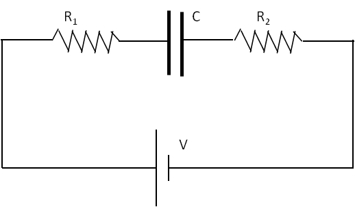
Find the time constant for the charging of capacitor in the circuit in Figure 34.77.
Figure 34.77.
Answer.
\(\tau = \left( R_1 + R_2 \right) C\text{.}\)
Solution.
The given circuit is simply a series \(RC\)-circuit with \(R = R_1 + R_2\) and \(C\) as given. Therefore, the time constant of this circuit will be \(\tau = \left( R_1 + R_2 \right) C\text{.}\)