Logo image

Physics Bootcamp

Section 34.16 Current and DC Circuits Bootcamp

Exercises Exercises

Electric Current

2. Drift of Electron Flow in a Thin Metal Wire.
Follow the link: Example 34.2.
3. Rate of Flow of Electrons in a Current-Carrying Copper Wire.
Follow the link: Exercise 34.1.5.2.
5. Surface Current Density of Current at the Surface of a Cylindrical Wire.
Follow the link: Example 34.3.
6. Surface Current Density of Flowing Charges on a Planar Surface.
Follow the link: Example 34.4.
8. Drift and Volume Current Density in a Thick Wire.
Follow the link: Example 34.5.
9. Current Density and Drift Speed in a Current Carrying Copper Wire.
Follow the link: Exercise 34.1.5.4.
11. Current Desity in a Current Carrying Copper Pipe.
Follow the link: Exercise 34.1.5.6.
12. Current Density in Oppositely Flowing Cylindrical Wire and Shell.
Follow the link: Exercise 34.1.5.7.
13. Current Through Different Parts of a Cross-Section of a Steel Wire.
Follow the link: Exercise 34.1.5.8.
15. (Calculus) Artificial Example of Current Density Varying Linearly Across Cross-Section of a Wire.
Follow the link: Exercise 34.1.5.9.
16. (Calculus) Artificial Example of Current Density That Drops With Distance From Axis.
Follow the link: Exercise 34.1.5.10.
17. (Calculus) Current Through a Wire with Current Density Varying Across Cross-section.
Follow the link: Exercise 34.1.5.11.

Ohm’s Law

18. Resistances of Wires Made from Different Metals.
Follow the link: Example 34.15.
19. Resistance from Resitivity, Length, and Thickness.
Follow the link: Example 34.16.
21. Temperature from Resistance Readings.
Follow the link: Example 34.14.
22. Charge Density at the Interface of Two Metals.
Follow the link: Example 34.19.
23. Resistivity and Conductivity from Ohm’s Law Application.
Follow the link: Exercise 34.3.4.2.
24. Resistivity and Conductivity from Ohm’s Law on a Slab.
Follow the link: Exercise 34.3.4.3.
25. Potential Drop Across and Electric Field in a Wire Carrying Current.
Follow the link: Exercise 34.3.4.4.
26. Current Density in a Wire from a Potential Difference across the Wire.
Follow the link: Exercise 34.3.4.5.
27. Drift Speed and Electric Field in two Metals Welded Together.
Follow the link: Exercise 34.3.4.6.
28. Electric Field in two Wires Welded Together and Carrying Currentr.
Follow the link: Exercise 34.3.4.7.
29. Current Density and Electric Field in a Current Carrying Wire.
Follow the link: Exercise 34.3.4.8.
30. Resistance of a Rectangular Slab in Three Different Directions.
Follow the link: Exercise 34.3.4.9.

Power Dissipation in a Resistor

32. Resistance of Heating Element from Power Consumed.
Follow the link: Exercise 34.4.1.
33. Resistance in Filaments of a 60-W Light Bulb.
Follow the link: Example 34.24.
34. Rise in Temperature of a Copper Rod Carrying Current.
Follow the link: Exercise 34.4.2.
35. Heating an Aluminum Rod by Passing a Current Through it.
Follow the link: Exercise 34.4.3.

Series and Parallel Circuits

36. Current and Electric Field in a Wire Connected Across a Battery.
Follow the link: Example 34.27.
37. Current, Voltage, and Power in Resistors in Series Circuit.
Follow the link: Example 34.30.
38. Dependence of the Terminal Voltage of Battery on the Load.
Follow the link: Example 34.32.
40. Voltage Source Needed For Delivering Required Power to Resitors in Series.
Follow the link: Exercise 34.6.4.2.
43. A Parallel Circuit of Three Resistors in Disguise.
Follow the link: Exercise 34.7.4.2.
44. Circuits with Series and Parallel Connections.
Follow the link: Example 34.42.
45. Equivalent Resistance of Resistors Connected in Series and in Parallel.
Follow the link: Exercise 34.8.1.
46. Voltage Difference Between Two Points in a Series-Parallel Circuit.
Follow the link: Exercise 34.8.2.
47. Equivalent Resistance of a Series/Parallel/Series Circuit.
Follow the link: Exercise 34.8.3.

Kirchhoff’s Rules

48. Circuit With Two Voltage Sources.
Follow the link: Example 34.56.
49. Numerical Bridge Circuit Example.
Follow the link: Example 34.61.
50. Finding Electric Potentials in a Bridge Circuit.
Follow the link: Example 34.63.

Charging and Discharging a Capacitor

52. Time for Discharging a Capacitor to Various Amounts.
Follow the link: Exercise 34.11.2.1.
53. Time Constant of an RC Circuit with two Resistors in Series to a Capacitor.
Follow the link: Exercise 34.11.2.2.
54. Numerical Example of Discharging a Capacitor.
Follow the link: Example 34.76.
55. Numerical Example of Charging a Capacitor.
Follow the link: Example 34.79.
56. Energy Dissipated in Charging a Capacitor in an RC Circuit.
Follow the link: Exercise 34.12.2.1.
57. Energy from Discharging a Capacitor.
Follow the link: Example 34.80.

Capacitors in Series and Parallel

59. Numerical Example of Capacitors in Series.
Follow the link: Example 34.82.
60. Numerical Example of Capacitors in Parallel.
Follow the link: Example 34.84.
61. Equivalent Capacitance for Capacitors Connected in Series and in Parallel.
Follow the link: Example 34.85.

Miscellaneous

62. Power Dissipation in a Battery with Internal Resistance.
A battery of EMF \(3\,\text{V}\) and internal resistance \(2\ \Omega\) is connected to a light bulb of resistance \(10\ \Omega\text{.}\) (a) Find the power dissipated in the battery. (b) What is the wattage of the bulb?
Answer.
(a) \(1/8\ \text{W}\text{,}\) (b) \(5/8\ \text{W}\text{.}\)
Solution 1. a
The resistors of the battery and the bulb are in series. Therefore, the current can be obtained by using the equivalent resistance.
\begin{equation*} I = \frac{3\:\text{V}}{(2+10)\:\text{W}} = \frac{1}{4}\:\text{A}. \end{equation*}
Hence, the power dissipated in the battery is
\begin{equation*} P_{\text{lost in battery}} = I^2\:R_{\text{internal}} = \frac{1}{16}\times 2 = \frac{1}{8}\:\text{W}. \end{equation*}
Solution 2. b
The wattage of the bulb is equal to the power dissipated in the bulb.
\begin{equation*} \text{Wattage of bulb } = I^2\;R_{\text{bulb}} = \frac{1}{16}\times 10 = \frac{5}{8}\:\text{W}. \end{equation*}
63.
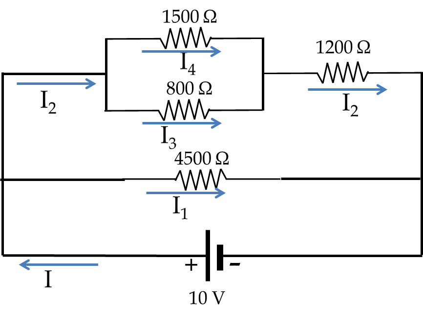
Find current through the \(800\, \Omega\) resistor in the circuit given in Figure 34.87.
Figure 34.87.
Answer.
\(3.79\, \text{mA}\text{.}\)
Solution.
This circuit is actually a series/parallel circuit in disguise. By moving around the resistors while keeping the unique electrical potential points in the system (i.e.m nodes), we can redraw the circuit to make the series/parallel/etc evident.
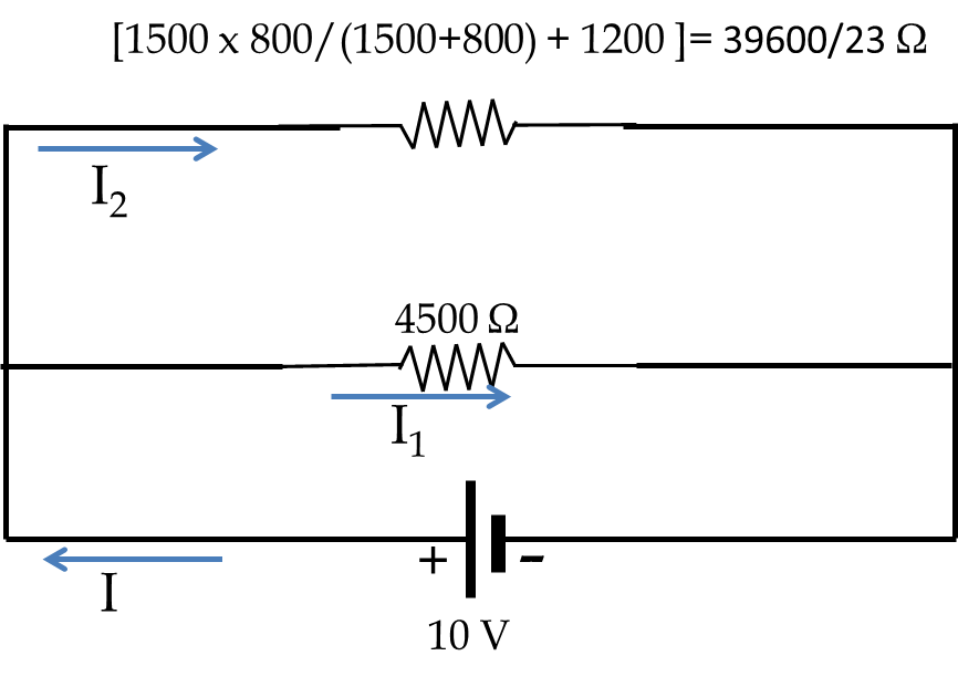
Figure 34.88.
With this drawing it is easy to see that the equivalent resistance would be
\begin{equation*} R = \left[ \left( \frac{1500\times 800}{2300} + 1200\right)^{-1} + \frac{1}{4500} \right]^{-1} = \frac{66000}{53}\:\Omega. \end{equation*}
Hence, the current \(I\) through the voltage source will be
\begin{equation*} I = \frac{V}{R} = \frac{10\:\text{V}}{66000/53\:\Omega} = 8.03\:\text{mA}. \end{equation*}
The current \(I\) divides into \(I_1\) and \(I_2\) and recombines making the circuit a circuit divider as shown in the figure below.
Figure 34.89.
Using the circuit divider formula we obtain both \(I_2\) and \(I_1\text{.}\)
\begin{align*} \amp I_2 = 8.03\:\text{mA}\times \frac{4500\:\Omega}{(4500 + 39600/23)\:\Omega} = 5.81\:\text{mA},\\ \amp I_1 = I - I_2 = 2.22\:\text{mA}. \end{align*}
Now, when you look into the branch in which the net current is \(I_2\) you find that this part also has a current divider circuit with \(I_2\) dividing into \(I_3\) and \(I_4\) in a parallel sub-circuit. Therefore, we obtain the current \(I_3\) through 800-Ohm resistor from the current divider equation, and \(I_4\) from the current conservation.
\begin{align*} \amp I_3 = 5.81\:\text{mA}\times \frac{1500\:\Omega}{(1500 + 800)\:\Omega} = 3.79\:\text{mA},\\ \amp I_4 = I_2 - I_3 = 2.02\:\text{mA}. \end{align*}
64.
Find current in each branch of the circuit in Figure 34.90.
Figure 34.90.
Hint.
This circuit does not simplify much. You will have a total of six currents.
65.
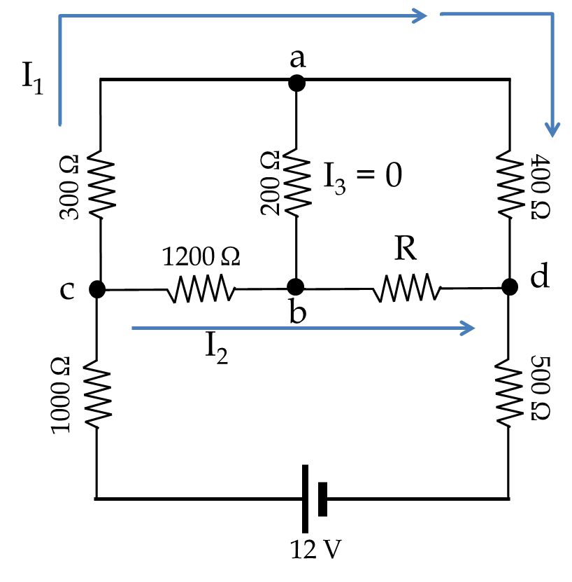
Find the unknown resistance \(R\) in Figure 34.91 such that current through \(200\, \Omega\) resistor is zero.
Figure 34.91.
Answer.
\(1600\, \Omega\text{.}\)
Solution.
When there is no current in \(200\, \Omega\) resistor, the potentials at a and b are equal. Hence, the drops in potential across c-a and c-b must be equal, and the same would be the case for potential drops in a-d and b-d. The currents in c-a and a-d will be equal since the current does not branch out, and the current in c-b and b-d will also be equal. Let \(I_1\) and \(I_2\) be currents in c-a-d and c-b-d branches respectively.
Figure 34.92.
\begin{align*} \amp V_c - V_a = V_c - V_a \ \ \Longrightarrow\ \ 300\:I_1 = 1200\: I_2,\\ \amp V_a - V_d = V_b - V_d \ \ \Longrightarrow\ \ 400\:I_1 = R\: I_2. \end{align*}
Solving these equations for \(R\) gives \(R = 1600\:\Omega\text{.}\)
66. Time Constant of an RC Circuit with Multiple Capacitors and Resistors.
Determine the time constant of the circuit in Figure 34.93. Use \(C_1 = 20\,\mu\text{F}\text{,}\) \(C_2 = 30\, \mu\text{F}\text{,}\) \(C_3 = 40\, \mu\text{F}\text{,}\) and \(R_1 = 2\, \text{k}\Omega\) , \(R_2 = 5\, \text{k}\Omega\text{,}\) \(R_3 = 10\, \text{k}\Omega\text{,}\) and \(R_4 = 4\, \text{k}\Omega\text{.}\)
Figure 34.93.
Answer.
\(47.6\, \text{ms}\text{.}\)
Solution.
The given circuit can be simplified to the series \(RC\) circuit with the equivalent resistance \(R\) and the equivalent capacitance \(C\text{.}\) The time constant of this series circuit will be equal to \(RC\) as we have worked out before. We need to figure out the equivalent capacitance and resistance.
Figure 34.94.
\begin{align*} \amp R = R_1 + \frac{R_4(R_2 + R_3)}{R_2 + R_3 + R_4} = \frac{98}{19}\:\textrm{k}\Omega,\\ \amp C = \left[ \frac{1}{C_1} + \frac{1}{C_2} + \frac{1}{C_3}\right]^{-1} = \left[ \frac{13}{120} \right]^{-1} = \frac{120}{13}\:\mu\textrm{F}. \end{align*}
Hence, the time constant will be
\begin{equation*} \tau = RC = \frac{98}{19}\:\textrm{k}\Omega\times \frac{120}{13}\:\mu\textrm{F} = 47.6\:\textrm{ms}. \end{equation*}
67.
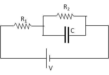
Determine the time constant of the circuit in Figure 34.95.
Figure 34.95.
Answer.
\(\frac{R_1R_2C}{R_1 + R_2}\text{.}\)
Solution.
For time-constant, we can look at discharging circuit instead by replacing the battery with just a conducting wire. The resulting circuit shows that any current from the capcitor will divide into the two resistors which form a parallel resistor network. Thus, effective resistance in the discharging circuit will be
\begin{equation*} R_\text{eff}^{-1} = R_1^{-1} + R_2^{-1}. \end{equation*}
Hence, the time constant will be \(R_\text{eff}\,C\text{.}\)
\begin{equation*} \tau = R_\text{eff}\,C = \frac{R_1R_2C}{R_1 + R_2}. \end{equation*}
68. Equivalent Resistance of Resistors Placed on Edges of a Cube.
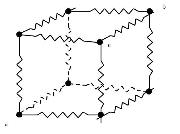
(a) Determine the equivalent resistance between points \(a\) and \(b\) of twelve identical resistors of resistance \(R\) each connected along the edge of a cube as shown in Figure 34.96. (b) Do the same between points \(a\) and \(c\text{.}\) Use symmetry instead of setting up Kirchhoff equations.
Figure 34.96.
Answer.
(a) \(\frac{5}{6} R\text{,}\) (b) \(\frac{3}{4}R\text{.}\)
Solution 1. a
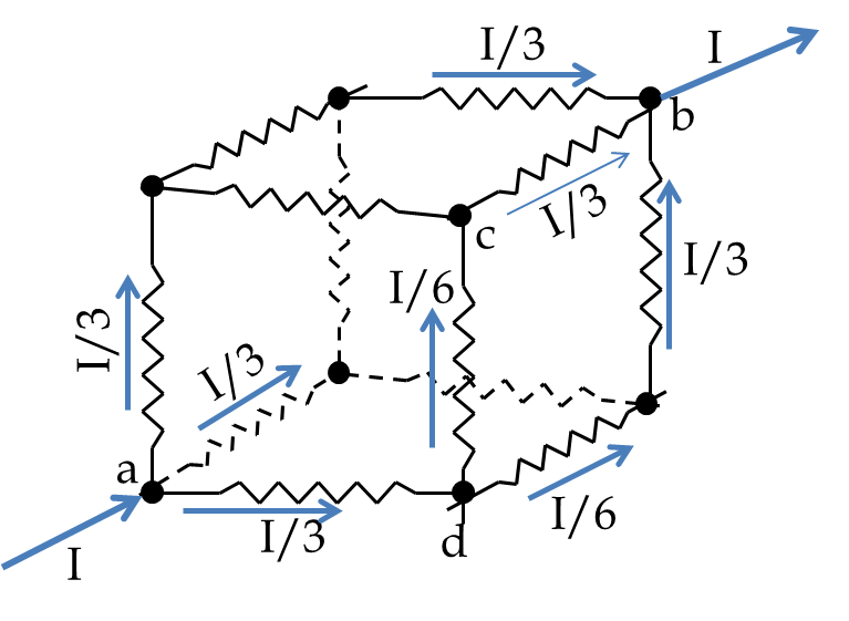
Use symmetry in the situation we can assign currents in different branches when a net current \(I\) enters a and exits b as shown in figure below.
Figure 34.97.
Now, we can find the voltage drop between a and b and the total current I by addign up the voltages in the path a-d-c-b.
\begin{equation*} V = \frac{1}{3} I R + \frac{1}{6} I R + \frac{1}{3} I R = \frac{5}{6} I R \equiv I R_{\textrm{eq}}. \end{equation*}
Therefore, the equivalent resistance between a and b will be \(\frac{5}{6} R\text{.}\)
Solution 2. b
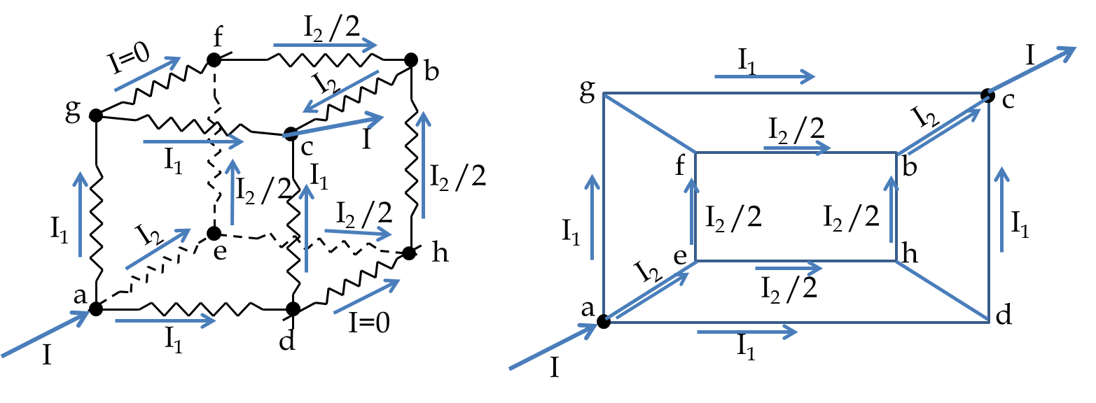
For this part we send a current at a of the structure and take out the current at c. Now the symmetry can be used to predict the relative currents in different branches as shown in the figure below. The digaram to the right makes the symmetry clearer.
Figure 34.98.
Equating the potential drops in the paths a-d-c and a-e-f-b-c gives us a relation between \(I_1\) and \(I_2\text{.}\) Using current conservation at a yields the currents in terms of the net current \(I\text{.}\) Now, voltage drop across a-c can be obtained by drops in a-d-c path, which can be used to deduce \(V/I\text{,}\) which gives the equivalent resistance \(\frac{3}{4}R\text{.}\)
69. Power Consumed by Resistors in Series/Parallel Circuit.
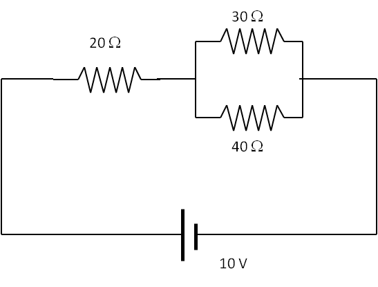
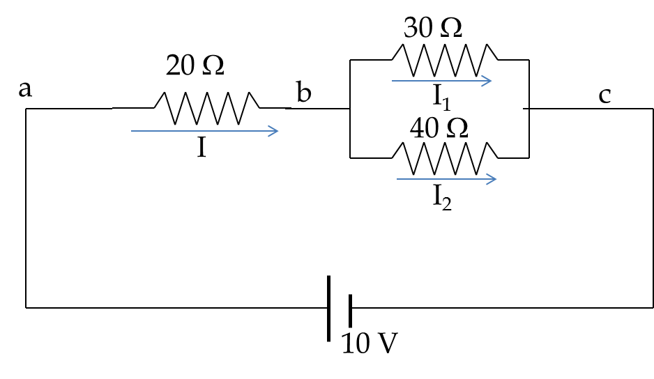
(a) Find current through each resistor in Figure 34.99. (b) How much power is consumed by each resistor? (c) If the battery can supply at most 200 Joules of energy, how long the current will flow in the circuit?
Figure 34.99.
Solution 1. a
Let us label points in the circuit where voltages are different.
Figure 34.100.
The equivalent resistance between a and c can be found readily to be
\begin{equation*} R_{\textrm{eq}} = 20 + \dfrac{30\times 40}{30+40} = \dfrac{260}{7}\:\Omega. \end{equation*}
Hence, current through the battery will be
\begin{equation*} I = \dfrac{V}{R_{\textrm{eq}}} = 10\times \dfrac{7}{260} = \dfrac{7}{26}\:\textrm{A}. \end{equation*}
The currents through 30 \(\Omega\) and 40 \(\Omega\) resistors are found by noting that current \(I\) splits into \(I_1\) and \(I_2\) in a parallel circuit. Therefore,
\begin{equation*} I_1 = \left( \dfrac{40}{30+40} \right)\:\dfrac{7}{26}\:\textrm{A} = \dfrac{2}{13}\:\textrm{A},\ \ \ I_2 = I-I_1 = \dfrac{3}{26}\:\textrm{A}. \end{equation*}
The power consumed by a resistor is found from the current through the resistor and its resistance by the formula \(P = I^2 R\text{.}\)
\begin{align*} \amp P_{20\Omega} = \left(\dfrac{7}{26} \right)^2 \times 20 = 1.45\:\textrm{W},\ \ P_{30\Omega} = \left(\dfrac{2}{13} \right)^2 \times 30 = 0.71\:\textrm{W},\\ \amp P_{40\Omega} = \left(\dfrac{3}{26} \right)^2 \times 40 = 0.53\:\textrm{W}. \end{align*}
Solution 2. b
The total power supplied by the battery is the product of its voltage and current through it, or equivalently the sum of the powers used by the resistors.
\begin{equation*} P = (7/26)\times 10 = 2.69\:\textrm{W}. \end{equation*}
Hence the battery will last for
\begin{equation*} \Delta t = \dfrac{\textrm{Energy in the battery}}{\textrm{Power usage}} = \dfrac{200\:\textrm{J}}{2.69\:\textrm{W}} = 74.3\:\textrm{sec}. \end{equation*}
70. Delivering Maximum Power to a Resistor.
A variable resistor \(R\) is connected to the terminals of a battery of fixed EMF \(V\) and internal resistance \(R_{in}\text{.}\) Find the value of variable resistor \(R\) for which the battery delivers maximum power to the resistor.
Answer.
\(R = R_\text{in}\text{.}\)
Solution.
This circuit has the two resistances in series (Draw to see it!), therefore current \(I\) through the external resistor \(R\) will be
\begin{equation*} I = \dfrac{V}{R + R_{\textrm{in}}}. \end{equation*}
This can be used in the formula for the power delivered to the external resistor to deduce the function \(P(R)\text{.}\)
\begin{equation*} P = I^2R = \left( \dfrac{V}{R + R_{\textrm{in}}} \right)^2\: R \end{equation*}
Setting the derivative of \(P\) with respect to \(R\) to zero locates the condition for the extremum of power.
\begin{equation*} \dfrac{dP}{dR} =0,\ \ \Longrightarrow\ \ \dfrac{V^2}{(R + R_{\textrm{in}})^2}- \dfrac{2V^2 R}{(R + R_{\textrm{in}})^3} ,\ \ \Longrightarrow\ \ R=R_{\textrm{in}}. \end{equation*}
Is it a maximum or a minimum? This is decided by examining the second derivative at that point. We take the second derivative of \(P\) with respect to \(R\) and evaluate it for \(R=R_{\textrm{in}}\text{.}\)
\begin{align*} \left.\dfrac{d^2P}{dR^2}\right|_{R=R_{\textrm{in}}} \amp = V^2\left[\dfrac{-1}{(R + R_{\textrm{in}})^3} + \dfrac{3(R_{\textrm{in}} - R)}{(R + R_{\textrm{in}})^4}\right]\\ \amp = -\dfrac{V^2}{8 R_{\textrm{in}} } \lt 0. \end{align*}
Therefore, when external resistance equals the internal resistance, the power delivered to the external resistor is maximum.
71. Resistance of a Conical-Shaped resistor.
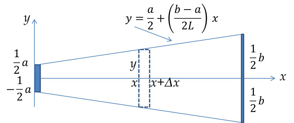
An aluminum rod of length \(L\) is shaved into a conical shape tapering linearly from radius \(a\) at one end to radius \(b\) at the other end as in Figure 34.101. Prove that the resistance in terms of the given dimensions and resistivity \(\rho\text{.}\)
Figure 34.101.
Answer.
\(4\rho L/\pi a b\text{.}\)
Solution.
Think of the rod as made up of thin disks put in series with each other.
Figure 34.102.
The resistance \(\Delta R\) of each disk depends on its width \(\Delta x\) and area of cross-section \(A\text{,}\) which is equal to \(\pi y^2\) for the disk at \(x\text{.}\) The radius of the disk given by \(y\) is related to the \(x\)-coordinate by the equation of the line as displayed in the figure.
\begin{equation*} \Delta R = \rho\:\dfrac{\Delta x}{\pi y^2} = \rho\:\dfrac{\Delta x}{\pi\left[\frac{a}{2} + (\frac{b-a}{2L}\: x) \right]^2}. \end{equation*}
Since the elements are in series connection with each other, the resistance of the rod will be obtained by summing up the resistances of the elements. In the limit of infinitesimal elements, the sum is replaced by an integral.
\begin{equation*} R = int_0^L\: \rho\: \dfrac{dx}{\pi\left[\frac{a}{2} + (\frac{b-a}{2L}\: x) \right]^2} = \dfrac{4\rho\:L}{\pi a b}. \end{equation*}
72. Equivalent Resistance.
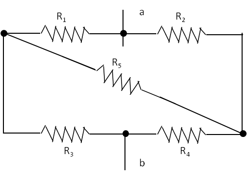
Find the equivalent resistance between \(a\) and \(b\text{.}\) You may connect a battery of voltage \(V\) across \(a\) and \(b\) and then solve for current through the battery. The \(R_{eq}\) will then be \(V/I\text{.}\)
Figure 34.103.
Solution.
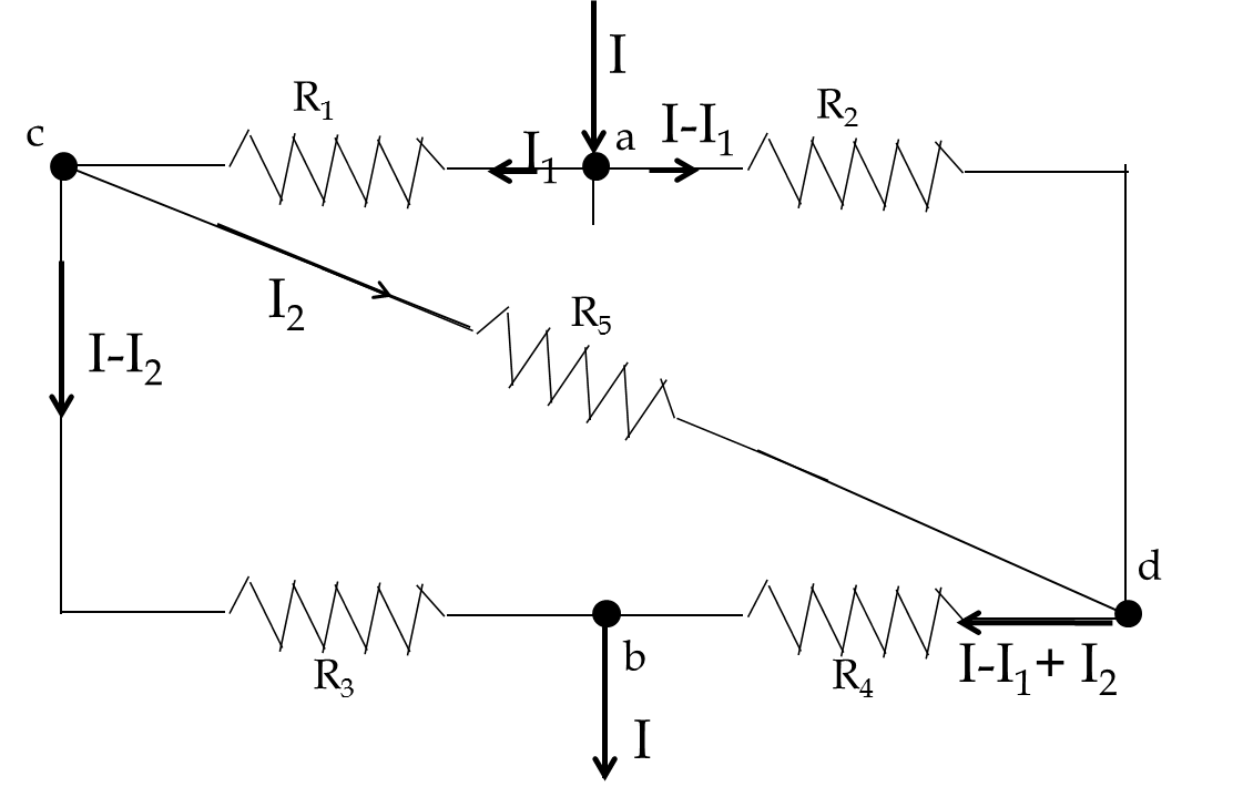
This is a bridge circuit. Let current \(I\) enter the circuit at a and exit at b, and there be a voltage difference of \(V\) between a and b. Let us assign currents in each branch, using KCL along the way to simplify the algebra. This is shown in the figure below.
Figure 34.104.
The voltage drop is \(V\) along paths a-c-b, a-d-b, and a-c-d-b.
\begin{align*} \amp V = I_1 R_1 + (I_1-I_2)R_3\ \ \ \ \ \amp (1)\\ \amp V = (I-I_1)R_2 + (I-I_1+I_2)R_4\ \ \ \ \amp (2)\\ \amp V = I_1R_1 +I_2 R_5 + (I-I_1+I_2)R_4\ \ \amp (3) \end{align*}
Solve (1) and (2) for \(I_1\) and \(I_2\) in terms of \(V\) and \(I\text{,}\) and the resistors.
\begin{equation*} I_1 = A\:V + B\:I,\ \ I_2 = C\:V + D\:I, \end{equation*}
where \(A\text{,}\) \(B\text{,}\) \(C\text{,}\) and \(D\) contain resistors only. Put these expression of \(I_1\) and \(I_2\) in (3) and simplify to find.
\begin{equation*} V = R_{\textrm{eq}}I \end{equation*}
where \(R_{\textrm{eq}}\) is the desired equivalent resistance in terms of the five resistances given. The algebra is left for the student to complete.
73. Capacitance of a Partially Filled Capacitor..
The space between two charged gold foil sheets, \(10\, \text{cm} \times 10\,\text{cm}\text{,}\) separated by a \(0.3\, \text{mm}\) is filled with a sheet of mica of thickness \(0.1\, \text{mm}\text{.}\) Find the capacitance. Use dielectric constant of mica to be \(7\text{.}\)
Answer.
\(4.13\,\text{pF}\text{.}\)
Solution.
Imagine inserting an imaginary infinitesimally thin plate just above mice. This device will create two capacitors in series, one with mica of thickness \(0.1\, \text{mm}\) and one of vacuum of thickness \(0.2\, \text{mm}\text{.}\) Let’s call their capacitances \(C_1\) and \(C_2\) respectively. Now,
\begin{equation*} \frac{1}{C} = \frac{1}{C_1} + \frac{1}{C_2}. \end{equation*}
Therefore.
\begin{equation*} C = \frac{C_1 C_2}{C_1 + C_2}. \end{equation*}
Now, we use numerical values to get
\begin{align*} C_1 \amp = \frac{\epsilon_0 \epsilon_r A}{d_1} =8.85\times 10^{-12} \frac{7 \times 100\times 10^{-4}}{0.1\times 10^{-1}} = 62\times 10^{-12}\,\text{F} \\ C_2 \amp = \frac{\epsilon_0 \epsilon_r A}{d_1} =8.85\times 10^{-12} \frac{1 \times 100\times 10^{-4}}{0.2\times 10^{-1}} = 4.43\times 10^{-12}\,\text{F} \end{align*}
Therefore
\begin{equation*} C = \frac{ 62 \times 4.43}{62+4.43}\, \text{pF} = 4.13\,\text{pF}. \end{equation*}
74. Capacitance of a Capacitor Filled with Two Dielectric Materials.
The space between two charged aluminum foils, \(15\) cm \(\times\) \(15\) cm, separated by \(2\) mm is filled with \(1\) mm thick mica and \(1\) mm paper. The foils are oppositely charged with charges \(\pm 10\ \mu\)C. (a) Find the capacitance. (b) Find the electric field in the mica and in the paper. (c) Evaluate the polarization of mica.
Answer.
(a) 0.48 nF, (b) \(|\vec E_{\textrm{mica}}| = 7.14\times 10^6\) N/C, \(|\vec E_{\textrm{paper}}| = 1.35\times 10^7\) N/C, (c) \(4.4\times 10^{-4}\ \textrm{C/m}^2\text{.}\)
Solution 1. a
Here the space between the plates is filled by two different dielectrics. The situation is equivalent to two capacitors in series. The capacitors in series add in inverses.
\begin{equation*} \dfrac{1}{C} = \dfrac{1}{C_1} + \dfrac{1}{C_2}, \end{equation*}
where \(C_1\) and \(C_2\) are capacitances of mica and paper filled capacitors
\begin{align*} \amp C_1 = K_1\:\dfrac{\epsilon_0\:A}{d} = 7\times \dfrac{8.85\times 10^{-12}\:\textrm{F/m}\times 0.0225\:\textrm{m}^2}{0.001\:\textrm{m}} = 1.4\:\textrm{nF},\\ \amp C_2 = K_2\:\dfrac{\epsilon_0\:A}{d} = 3.7\times \dfrac{1.4\:\textrm{nF}}{7} = 0.74\:\textrm{nF} \end{align*}
Hence,
\begin{equation*} \dfrac{1}{C} = \dfrac{1}{1.4\:\textrm{nF}} + \dfrac{1}{0.74\:\textrm{nF}},\ \ \Longrightarrow\ \ C = \dfrac{1.4\:\textrm{nF}\times 0.74\:\textrm{nF} }{1.4\:\textrm{nF} + 0.74\:\textrm{nF}} = 0.48\:\textrm{nF}. \end{equation*}
Solution 2. b
Let us find the electric field when there is no dielectric first. For two oppositely charged plates with nothing between the plates, the electric field in the space between the plates will have the following magnitude,
\begin{equation*} E_0 = \dfrac{Q}{\epsilon_0 A} = 5\times 10^7\:\textrm{N/C}. \end{equation*}
Therefore, the electric field in the mica and paper will be reduced by the corresponding dielectric constant,
\begin{align*} \amp E_{\textrm{mica}} = \dfrac{E_0}{K_{\textrm{mica}}} = \dfrac{5\times 10^7\:\textrm{N/C}}{7} = 7.14\times 10^6\:\textrm{N/C}\\ \amp E_{\textrm{paper}} = \dfrac{E_0}{K_{\textrm{paper}}} = \dfrac{5\times 10^7\:\textrm{N/C}}{3.7} = 1.35\times 10^7\:\textrm{N/C} \end{align*}
Solution 3. c
We can find the polarization of mica from the electric field inside mica.
\begin{align*} P_{\textrm{mica}} \amp = \epsilon_0\:(K_{\textrm{mica}} - 1)\:E_{\textrm{mica}}\\ \amp = 8.85\times 10^{-12}\times 7\times 7.14\times 10^6 = 4.4\times 10^{-4}\:\textrm{C/m}^2. \end{align*}