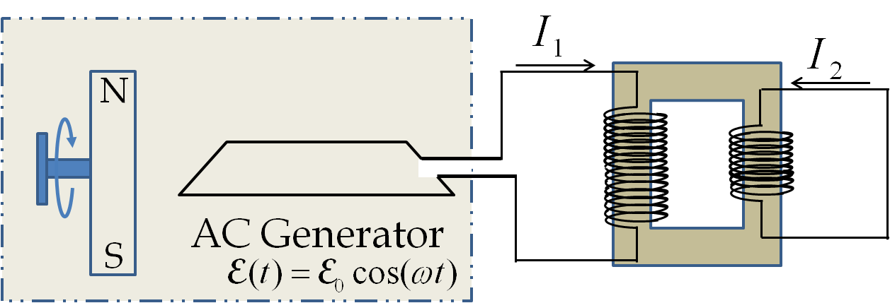
A transformer is a device that usually consists of two coils of wires known as the primary and the secondary. A transformer is used to either step up or step down the EMF in the primary. We will see how that happens.
The coils of primary and secondary are either interwoven or wound around a soft iron core made up of laminated thin iron sheets to reduce the Eddy currents as shown in
Figure 41.54. The magnetic fields of the currents in the the coils are guided through a magnetic core so that the two coils have a mutual inductance
\(\mathcal{M}\text{.}\)
The changing currents in the two circuits will influence each other as we can see by writing the Faraday’s loop rule for the two circuits. Let \(I_1(t)\) and \(I_2(t)\) be the currents in the two circuits and \(L_1\) and \(L_2\) be the self-inductance of the two coils. Then, we get the following equations for the two circuits by taking into account the effects of the self and the mutual inductances of the two circuits.
\begin{align}
\amp L_1\frac{dI_1}{dt} \pm M \frac{dI_2}{dt} = \mathcal{E}_0\; \cos(\omega t)\ \ \text{(Primary)}\tag{41.45}\\
\amp L_2\frac{dI_2}{dt} \pm M \frac{dI_1}{dt} = 0\ \ \text{(Secondary)}\tag{41.46}
\end{align}
The signs of the terms depend on the directions of the currents. For concreteness we will pick the negative sign for the term containing the mutual inductance. Let us now examine these equations for an ideal transformer. Suppose the two coils are coupled so that the same magnetic field lines pass through both the coils. The iron core helps with this coupling. We have determined the mutual inductance of one coil inside the other in inductance chapter. Suppose the two coils have the same radius \(a\text{,}\) and let \(l_1\) and \(l_2\) be the lengths of the two coils, and \(N_1\) and \(N_2\) be the total number of turns of the two coils. The formulas for the inductances would be
\begin{align*}
\amp L_1 = \mu \pi a^2 \frac{N_1^2}{l_1}, \\
\amp L_2 = \mu \pi a^2 \frac{N_2^2}{l_2}, \\
\amp \mathcal{M} = \mu \pi a^2 \frac{N_1N_2}{l_2}.
\end{align*}
Here
\(\mu\) is the magnetic permeability of the material over which the coils have been wound and I have assumed that
\(l_2\lt l_1\text{.}\) Using these inductances in the equation, Eq.
(41.46) with the negative sign for
\(\pm\) chosen for concreteness, for the circuit for the secondary gives
\begin{equation*}
L_2\frac{dI_2}{dt} - M \frac{dI_1}{dt} = 0\ \ \Longrightarrow\ \ \frac{d}{dt}\left(N_1I_1 - N_2I_2 \right) = 0.
\end{equation*}
Therefore,
\begin{equation*}
N_1I_1 - N_2I_2 = \text{constant}.
\end{equation*}
The constant can be set to zero if the zero current in one circuit coincides with the zero current in the other circuit. This gives us the following relation between the currents in the two circuits.
\begin{equation}
N_1I_1 = N_2I_2.\tag{41.47}
\end{equation}
Therefore, the coil with more loops will have less current. That is, if the primary has 100 loops and the secondary 50 loops, then the secondary will have twice as much current as the primary.
The ideal circuit shown in
Figure 41.54 has no place energy can be used up. Any work done by the external agent in the generator goes towards building up the current in the circuits. Every circuit has some resistance where energy is dissipated. To include the dissipation of energy let us add a resistive load such as an electric light bulb or a heater in the secondary as shown in
Figure 41.55. In this case, the work done by the agent in the generator will be expended in the load.
As you have known from your study of dynamic fields that voltage concept is not applicable when you have changing magnetic field, which you have in the transformer. To compare the “voltage” across the two coils in a transformer, we will make the assumption that there is no changing magnetic field outside the generator and the coils. As we have seen before, this assumption allows us to consider the electric field outside the generator and the coils a conservative field which can be used to define the potential difference across the primary and the secondary coils. Let the voltages across the primary and secondary be denoted by
\(V_1\) and
\(V_2\) as shown in
Figure 41.55. The power dissipated in the secondary must equal the power produced in the primary. This gives
\begin{equation}
I_1 V_1 = I_2 V_2. \tag{41.48}
\end{equation}
Using Eq.
(41.47) we find that the voltages on the two sides of an ideal transformer will be in proportion to the number of turns:
\begin{equation}
\frac{V_2}{V_1} =\frac{N_2}{N_1}. \tag{41.49}
\end{equation}
If \(N_2 \lt N_1\text{,}\) then \(V_2 \lt V_1\text{,}\) the voltage in the secondary would be less than the voltage in the primary. We call this type of transformer a step-down transformer. On the other hand, if \(N_2>N_1\text{,}\) then \(V_2>V_1\text{,}\) the voltage in the secondary would be more than the voltage in the primary. This transformer is called a step-up transformer. High voltage sources are constructed this way.
Equation
(41.49) can also be deduced by assuming that the magnetic fields lines through each loop of the primary also pass through each loop of the secondary so that the rates of change of magnetic flux through primary and secondary per loop are equal. Then, the ratio of the EMF induced in the two circuits will be proportional to the number of turns.
\begin{align*}
\amp \mathcal{E}_1 = N_1 \left( \frac{d\Phi_B}{dt} \right)_{\text{one loop}}\\
\amp \mathcal{E}_2 = N_2 \left( \frac{d\Phi_B}{dt} \right)_{\text{one loop}}\\
\amp \ \ \ \Longrightarrow\ \ \frac{\mathcal{E}_2}{\mathcal{E}_1} = \frac{N_2}{N_1}.
\end{align*}
Transformers play important role in transmission lines. Usually power plants are located away from cities. To reduce the power loss in the transmission lines, the power companies send power at high voltage (often several kilovolts) and then use step down transformers to bring the voltage down to the \(120\text{ V}\) or \(240\text{ V}\) for delivery to homes and businesses.


