   
Logo image

Physics Bootcamp

Section 41.3 Inductive AC Circuits

Every circuit with varying current will have inductive effect due to the back emf from the self-inductance of the circuit. Usually, back emf effect at frequency of an AC circuit is not significant. But if we insert coils or inductors with significant inductance, the inductive effective can be made to be significant even at the frequencies of the regular AC supply line. We call these circuits inductive circuits or RL-circuits.
We have encountered them before, but here we will look at them a little differently, focusing on the current and voltage relations. Along the way, we will also encounter a new property of AC circuits, called impedance of a circuit.
Consider a simple circuit that has a rsistor of resistance \(R\) and an inductor of inductance \(L\) connected in series with a AC source as shown in Figure 41.13 with phase constant chosen as reference zero.
\begin{equation} V(t) = V_0\cos(\omega t)\tag{41.15} \end{equation}
We are interested in the current in the circuit after the initial transiets have died out and steady state has set in the circuit.
Figure 41.13.
By applying Faraday’s law or Kirchhoff’s loop rule to the loop of the circuit, we show in Subsection 41.3.1 below that steady state current in the circuit will also be sinusoidal.
\begin{equation*} I(t) = I_0 \cos(\omega t + \phi_I), \end{equation*}
where amplitude and phase are given by
\begin{align} \amp I_0 = \frac{V_0}{\sqrt{R^2 +(\omega L)^2}},\tag{41.16}\\ \amp \phi_I = -\tan^{-1}\left(\frac{\omega L}{R}\right).\tag{41.17} \end{align}
The quantity \(\omega\,L\) is the reactance \(X_L\) of the capacitor.
\begin{equation*} X_L = \omega\,L. \end{equation*}
The ratio of current amplitude \(I_0\) to the voltage amplitude \(V_0\) is like an “effective resistance” of the circuit seen by the EMF source. We call it impedance of the circuit and usually denote by absolute \(|Z|\text{.}\)
\begin{equation*} |Z| = \dfrac{V_0}{I_0} = \sqrt{R^2 + X_L^2} = \sqrt{R^2 +(\omega L)^2}. \end{equation*}
The absolute sign is not needed for the symbol here. The reason for using absolute sign will become clear when we introduce complex number notation for voltage and current. In that case, we will define a complex impedance \(Z\text{,}\) which includes both amplitude ratio of the voltage to current and the phase difference between the voltage and current.
Staying with real number representation of the voltages and currents, the phase difference between the phase of source voltage and current through the source will be
\begin{equation*} \phi_Z = \phi_{V} - \phi_{I}. \end{equation*}
With \(\phi_V = 0\text{,}\) chosen as zero of phase of all sinusoidal signals in the circuit, and \(\phi_I\) in Eq. (41.17), we get the phase shift of current in relation to the phase of the source voltage to be
\begin{equation*} \phi_Z = \tan^{-1}\left(\frac{\omega L}{R}\right). \end{equation*}

Subsection 41.3.1 Series RL Circuit

For our first example, we consider a circuit containing a resistor (\(R\)) and an inductor (\(L\)) driven by a sinusoidal EMF as shown in the figure. Using voltage drops across each element, we get the following Faraday loop equation.
\begin{equation} V_0\: \cos(\omega t) -L\frac{dI}{dt} - R I = 0. \tag{41.18} \end{equation}
We will write this equation as
\begin{equation} \frac{dI}{dt} + \dfrac{R}{L} I = \dfrac{V_0}{L}\, \cos(\omega t).\tag{41.19} \end{equation}
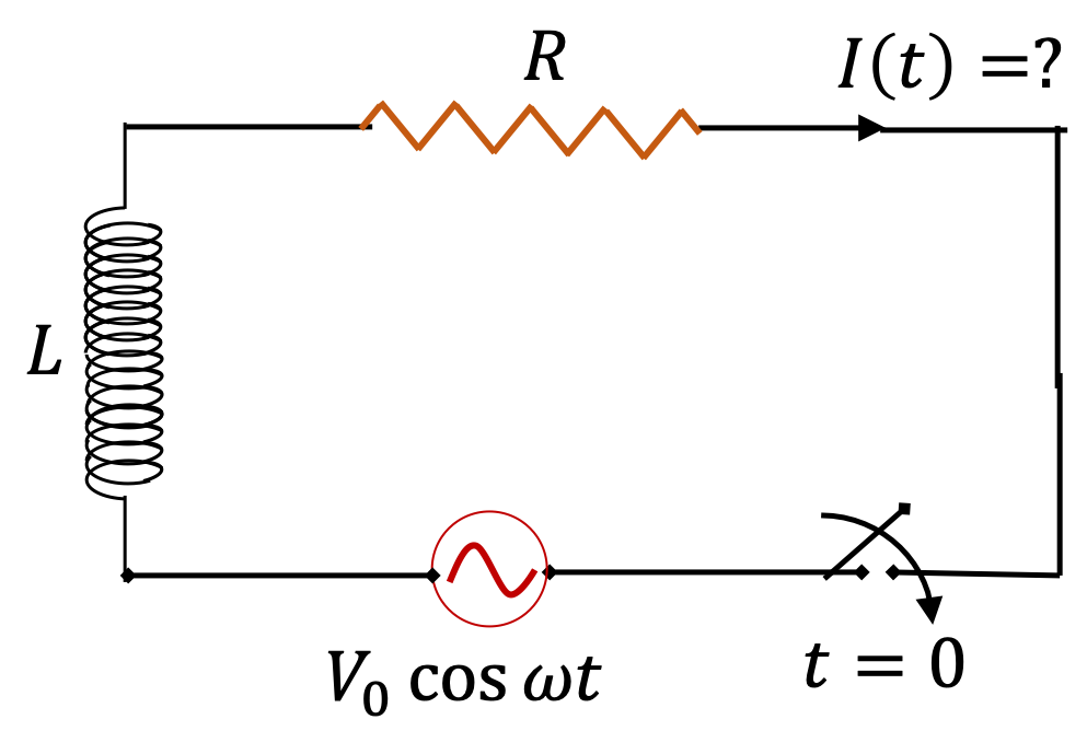
When switch is closed at \(t=0\text{,}\) there is a transient behavior of the circuit, where the current in the circuit does not oscillate with the same frequency as the frequency of the driving EMF. But, after some time (here \(t \gt \gt L/R \)) a steady state is reached, and thereafter, current in the circuit oscillates with the same frequency as the frequency of the driving EMF. Therefore, we can write the steady state solution of Eq. (41.19) in the following form that has two unknowns the amplitude \(I_0\) and phase constant \(\phi_I\text{.}\)
\begin{equation} I(t) = I_0\: \cos(\omega t+\phi_I).\ \ \ \text{(Steady state)} \tag{41.20} \end{equation}
To find \(I_0\) and \(\phi_I\text{,}\) we substitute this solution in Eq. (41.19) to obtain
\begin{equation*} -L\:\omega\: I_0\: \sin(\omega t+\phi_I) + RI_0\: \cos(\omega t+\phi_I) = V_0\: \cos(\omega t). \end{equation*}
Now, we expand the trigonometric functions and rearrange terms to obtain the following.
\begin{align*} \amp \left[ V_0 + L\:\omega\: I_0\: \sin\phi_I - R\: I_0\: \cos\phi_I \right] \cos(\omega t)\\ \amp \ \ \ \ \ \ \ + \left[ L\:\omega\: I_0\: \cos\phi_I - R\: I_0\: \sin\phi_I \right] \sin(\omega t) = 0. \end{align*}
In this equation, the coefficients of \(\cos(\omega t)\) and \(\sin(\omega t)\) must be independently zero since they are orthogonal functions. This can be shown by multiplying this equation by \(\cos(\omega t)\) and integrating over one period. You should do this step. you will find that this integration leads to the conclusion that the coefficient of the cosine term must be zero. Similarly, when you multiply by \(\sin(\omega t)\) and integrate over one period, you find that the coefficient of the sine term must be zero.
\begin{align} \amp V_0 + L\:\omega\: I_0\: \sin\phi_I - R\: I_0\: \cos\phi_I = 0. \tag{41.21}\\ \amp L\:\omega\: I_0\: \cos\phi_I - R\: I_0\: \sin\phi_I = 0. \tag{41.22} \end{align}
Therefore, we get the following for the phase constant of current
\begin{equation*} \tan\phi_I = -\frac{\omega L}{R}, \end{equation*}
from which we get sine and cosine of \(\phi_I\text{.}\)
\begin{align*} \amp \cos\phi_I = \frac{R}{\sqrt{R^2 +(\omega L)^2}}.\\ \amp \sin\phi_I = -\frac{\omega L}{\sqrt{R^2 +(\omega L)^2}}. \end{align*}
Putting these expressions for \(\sin\phi_I\) and \(\cos\phi_I\) in Eq. (41.21), we find \(I_0\text{.}\)
\begin{equation*} I_0 = \frac{V_0}{\sqrt{R^2 +(\omega L)^2}} \end{equation*}
Summarizing, our results, we found current in the circuit is \(I=I_0\cos(\omega t + \phi_I)\) with
\begin{equation*} I_0 = \frac{V_0}{\sqrt{R^2 +(\omega L)^2}},\ \ \ \ \phi_I = -\tan^{-1}\left(\frac{\omega L}{R}\right) \end{equation*}

Remark 41.14. Impedance of series RL Circuit.

The ratio of the amplitude of the voltage of the source to that of the current through the source has units of resistance; it consists of contributions from the inductance and the frequency. This quantity “acts” like an overall resistance in the circuit and is called the amplitude of impedance or simply impedance of the circuit, denoted usually by the letter \(|Z|\text{.}\)
The amplitude of the impedance does not have the information of the phase difference between the voltage and the current. The complete impedance is defined to contain both of these informations into one complex quantity we will study in the next section. Here, the amplitude of the impedance of the RL-circuit is found to be
\begin{equation*} |Z| = \frac{\text{Amplitude of Voltage}}{\text{Amplitude of Current}} = \sqrt{R^2 +(\omega L)^2}. \end{equation*}
Negative of the phase of current, \(I(t)\text{,}\) relative to the source \(V(t)\) is called phase of the impedance. Denoting this phase by \(\phi_Z\text{,}\) we have
\begin{equation*} \phi_Z = \tan^{-1}\left(\frac{\omega L}{R}\right). \end{equation*}

Remark 41.15. RL Circuit at High and Low Frequencies.

  1. High frequency ( \(\omega\ \rightarrow\ \infty\) Limit)
    As frequency of the driving EMF is raised, we note that the inductive reactance increases without bound, and hence the resistor becomes less and less important in the RL-circuit. At very high frequencies, an RL-circuit acts purely inductive with phase constant of current, \(\phi_I\text{,}\) reaching close to \(-\pi/2\) radians and the amplitude \(I_0\) given by simply ignoring the resistance in the circuit, \(I_0 \approx V_0/\omega L\text{.}\)
  2. Low frequency ( \(\omega\ \rightarrow\ 0\) Limit)
    At low frequency the circuit becomes more like a DC circuit. Hence, the inductance becomes less important since a back EMF requires a changing magnetic flux. The current in the circuit will be in-phase with the driving EMF, i.e., \(\phi_I \rightarrow 0\text{,}\) and the amplitude \(I_0\) is obtained by ignoring the inductor altogether, i.e., \(I_0\ \approx V_0/R\text{.}\)

Example 41.16. Numerical Inductive Circuit Example.

A \(50\text{-mH}\) inductor with internal resistance \(0.2\, \Omega\) is connected across the terminals of a \(5\text{-V}\) AC source (i.e. \(V_\text{rms} = \frac{V_0}{\sqrt{2}} = 5\text{ V}\)) of frequency \(60\text{ Hz}\text{.}\) Find
  1. the reactance of the inductor,
  2. the amplitude of impedance of the circuit,
  3. the current amplitude,
  4. the phase constant for current.
Answer.
(a) \(18.8\: \Omega \text{,}\) (b) \(18.9\: \Omega\text{,}\) (c) \(375\:\text{mA}\text{,}\) (d) \(-89.4^{\circ}\text{.}\)
Solution.
Using formulas for the corresponding quantities we get
  1. \begin{equation*} X_L = 2\pi f L = 2\pi\times 60\:\text{Hz}\times 50\:\text{mH} = 18.8\: \Omega. \end{equation*}
  2. \begin{equation*} |Z| = \sqrt{R^2 + X_L^2} = \sqrt{0.2^2 + 18.8^2} = 18.9\: \Omega. \end{equation*}
  3. \begin{equation*} I_0 = \dfrac{V_0}{|Z|} = \dfrac{\sqrt{2}V_{\text{rms}}}{Z} = \dfrac{\sqrt{2}\times 5\:\text{V}}{18.9\: \Omega} = 375\:\text{mA}. \end{equation*}
  4. \begin{equation*} \phi_I = -\tan^{-1}\left(\dfrac{\omega L}{R} \right) = -\tan^{-1}\left(\dfrac{18.8\: \Omega}{0.2\: \Omega} \right) = -89.4^{\circ}. \end{equation*}

Example 41.17. Current and Voltage Drops Across Resistor and Inductor in Inductive Circuit.

A \(300\text{-}\Omega\) and \(0.2\text{-H}\) inductors connected in series to an AC source. The voltage across the resistor is found to be \((30\ \text{V})\ \cos(200\, t)\) where \(t\) is time in seconds.
  1. Find the amplitude and phase of the current in the circuit.
  2. Find the amplitude and phase of the voltage across the inductor.
  3. Find the amplitude and phase of the voltage of the source.
Answer.
(a) \(100\text{ mA},\ 0^{\circ}\text{,}\) (b) \(4\text{ V},\ 90^{\circ}\text{,}\) (c) \(30.3\text{ V}, 7.6^{\circ}\)
Solution 1. a
The current and voltage across a resistor are in-phase. Let the current through the resistor be denotes as \(I = I_0\:\cos(\omega t + \phi_I)\text{.}\) From the given voltage across the resistor we obtain
\begin{equation*} \phi_I = 0,\ \ I_0 = \dfrac{V_{0R}}{R} = \dfrac{30\: \text{V}}{300\:\Omega} = 0.1\:\text{A}. \end{equation*}
This current flows through all elements of the circuit.
\begin{equation*} I(t) = (0.1\:\text{A})\:\cos(200\, t). \end{equation*}
Solution 2. b
To find the amplitude of the voltage across the inductor we multiply the amplitude of the current, which is \(0.1\:\text{A}\text{,}\) and the reactance of the inductor.
\begin{equation*} V_{0L} = I_0\:X_L = 0.1\:\text{A}\times 200\:\text{s}^{-1}\times 0.2\:\text{H} = 4\:\text{V}. \end{equation*}
The phase of the voltage across an inductor is \(90^{\circ}\) ahead of the phase of the current. The phase of the current is set from the given data on the phase of the voltage across the resistance, which is zero here. Therefore, if we write \(V_L\) as \(V_L(t) = V_{0L}\:\cos(\omega t + \phi)\text{,}\) then \(\phi = 90^{\circ}\text{.}\) [Recall the phrase: ELI the ICE man, meaning EMF leads current in L and current leads EMF in C.]
Solution 3. c
To find the amplitude of the voltage of the source we will multiply the amplitude of the current and the impedance amplitude \(|Z|\) of the circuit. The impedance here is
\begin{equation*} |Z| = \sqrt{(300\:\Omega)^2 + (200\:\text{s}^{-1}\times 0.2\:\text{H})^2} = 303\:\Omega. \end{equation*}
Therefore the amplitude of the EMF of the source will be
\begin{equation*} V_0 = 0.1\:\text{A} \times 303\:\Omega = 30.2\:\text{V}. \end{equation*}
If we write the voltage of the source as \(V_0\:\cos(\omega t + \phi_V)\text{,}\) then this phase is the phase of voltage with respect to the zero phase for the current. Therefore, \(\phi_V\) will be given by
\begin{equation*} \phi_V = \tan^{-1}\left(\dfrac{X_L}{R} \right), \end{equation*}
where note the minus sign is not there since now we are writing \(\phi_V\) as phase of voltage with respect to the current in place of phase of the current with respect to the voltage.
\begin{equation*} \phi_V = \tan^{-1}\left(\dfrac{40\:\Omega}{300\:\Omega} \right) = 7.6^{\circ}. \end{equation*}

Exercises 41.3.2 Exercises

1. RL Circuit with a Sine Voltage Source.

Suppose the voltage source for a series RL-circuit were given as \(V_0 \sin(\omega t)\) instead of cosine worked out in this section. Find the expression for current amplitude and phase constant.
Solution.
The equation of motion of the circuit will be
\begin{equation*} L\dfrac{dI}{dt} + RI = V_0\:\sin(\omega t). \end{equation*}
Now, let the solution be in the form \(I(t) = A\:\cos\omega t + B\sin\omega t\) and obtain \(A\) and \(B\text{.}\) Alternately, you can use the form \(I(t) = I_0 \:\sin(\omega t + \phi)\) and solve for \(I_0\) and \(\phi\text{.}\)