   
Logo image

Physics Bootcamp

Section 34.7 Resistors in Parallel

We say that two resistors \(R_1\) and \(R_2\) are connected in parallel if a current entering the combination splits and recombines immediately after going through each of the resistors as shown in Figure 34.35. The two resistors in parallel circuit are also called two branches of the circuit and points \(a\) and \(b\) where they split or join are called junctions or nodes.
Another property to note of resistors in parallel is that the potential drops across each resistor is same for all resitors in parallel since every resistor is connected to same junction points on the two ends.
Figure 34.35. Two resitors connected in parallel. Current \(I\) entering the combination at junction \(a\) splits with separate currents entering the two resitors, which then immediately combine at junction \(b\) after exiting each resitor. Also, potential drop each resitor is same, viz., \(\Delta \phi_1 = \Delta\phi_2 = \phi_a - \phi_b\text{.}\)

Subsection 34.7.1 Potential Drop Across Resistors in Parallel

In Figure 34.35, the resitors in parallel are connected to a voltage source such that we set up the same potential differece across both resistors.
\begin{equation} \Delta \phi_1 = \Delta \phi_2 = \phi_a - \phi_b = V.\tag{34.26} \end{equation}

Subsection 34.7.2 Currents in Resitors in Parallel

Applying Ohm’s law to the two resistors separatelty gives us currents through the individual resitors immediately.
\begin{align} I_1 \amp = \frac{\Delta\phi_1}{R_1} = \frac{V}{R_1}\tag{34.27}\\ I_2 \amp = \frac{\Delta\phi_2}{R_2} = \frac{V}{R_2} \tag{34.28} \end{align}
These show that if \(R_1 \gt R_2\text{,}\) then \(I_1 \lt I_2\text{.}\) That is, higher current will flow through the branch with smaller resistance. If a branch has no resistance, then there will be no current will be left to flow through any other branch. Such as branch is called a short in the circuit.
Since a total current \(I\) comes into junction \(a\) and currents \(I_1\) and \(I_2\) leave and no charge accumates at \(a\text{,}\) we can apply conservation of charge to conclude the following current conservation at each junction.
\begin{equation*} I - I_1 - I_2 = 0, \end{equation*}
that is, overall current in the circuit is
\begin{equation} I = I_1 + I_2 = \frac{V}{R_1} + \frac{V}{R_2} = V \left(\frac{1}{R_1} + \frac{1}{R_2} \right) .\tag{34.29} \end{equation}
This shows that resitors in parallel divide up the total current among themselves. That is why we often refer to parallel resitors as current dividers. Solving this for \(V\) and using it in Eqs. (34.27) and (34.28), we find current in each branch in terms of the total current entering or exiting the parallel resistors. After simplification we get the folloing useful formulas.
\begin{align} I_1 \amp = I\,\frac{R_2}{R_1+R_2},\tag{34.30}\\ I_2 \amp = I\,\frac{R_1}{R_1+R_2}. \tag{34.31} \end{align}
Note the resistor in the numerator of each formula is the resitor in the other branch. Therefore, if other branch 2 has more resistance than branch 1, more current will flow in branch 1.

Subsection 34.7.3 Equivalent Resistor of Resistors in Parallel

Eq. (34.29) can be written in the following way, where voltage across the parallel combination is equal to the total current and a resistor, which is called equivalent resistor of the combination, \(R_\text{eqiv}\) .
\begin{equation*} V = I\left( \frac{1}{R_1} + \frac{1}{R_2} \right)^{-1} \equiv I R_\text{equiv}. \end{equation*}
The total current and total voltage related this way implies that the parallel combination of resistors “act” as if there was a single resitor of an equivalent resistance. We will also denote this equivalent resistance by \(R_\text{parallel}\) as illustrated in Figure 34.36.
\begin{equation} R_\text{parallel} = \left( \frac{1}{R_1} + \frac{1}{R_2} \right)^{-1} \equiv R_\text{equiv}.\tag{34.32} \end{equation}
This can be written in calculationally more friendly way,
\begin{equation} R_\text{parallel} = \frac{R_1 R_2}{R_1 + R_2}.\tag{34.33} \end{equation}
Figure 34.36. An equvalent circuit of two resitors connected in parallel. The resitors between the common junctions \(a\) and \(b\) can be replaced by \(R_\text{equiv}\) without affecting anything outside of the resitors that have been combined if \(R_\text{equiv} = R_\text{parallel} = \left( \frac{1}{R_1} + \frac{1}{R_2} \right)^{-1} \text{.}\)
We will often write Eq. (34.32) as an inverse resistance, i.e., a conductance relation.
\begin{equation} \frac{1}{R_\text{parallel}} = \frac{1}{R_1} + \frac{1}{R_2} \Longleftrightarrow G_\text{parallel} = G_1 + G_2,\tag{34.34} \end{equation}
where I have used the inverse relation between conductance \(G\) and resistance \(R\text{.}\)
\begin{equation*} G = \frac{1}{R}. \end{equation*}
For \(N\) resistors in parallel, you can show that
\begin{equation} \frac{1}{R_\text{parallel} } = \frac{1}{R_{1}} + \frac{1}{R_{2}} + \cdots + \frac{1}{R_{N}},\tag{34.35} \end{equation}
and the following for the conductances.
\begin{equation} G_\text{parallel} = G_1 + G_2 + \cdots + G_N.\tag{34.36} \end{equation}
Hence, conductances add in a parallel circuit. Earlier, we found that resistances add up in series.

Example 34.37. A Current Divider.

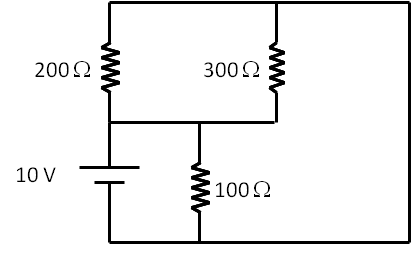
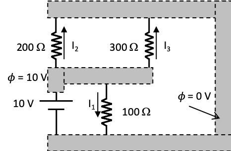
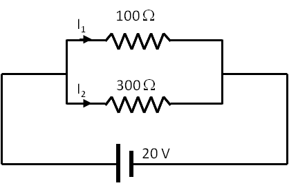
Consider the circuit given in Figure 34.38.
(a) Find percentage of current that passes through each resistor.
(b) Find equivalent resitance across the voltage source.
(c) Find current through the voltage source.
(d) Find current in each resistor.
Figure 34.38.
Answer.
(a) \(75\%,\ 25\%\text{,}\) (b) \(75\ \Omega \text{,}\) (c) \(267\text{ mA}\text{,}\) (d) \(67\text{ mA},\ 200\text{ mA}\text{.}\)
Solution 1. (a)
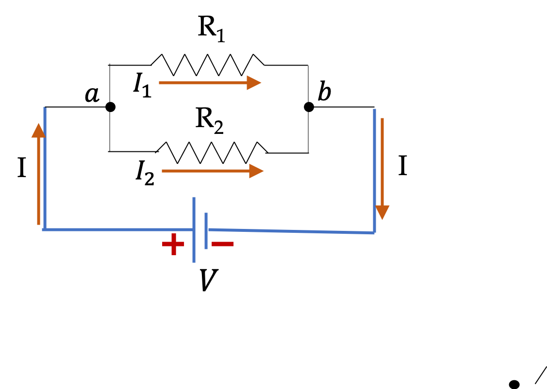
(a) In this example, current \(I_1\) will be more than current \(I_2\) since \(I_1\) passes through the smaller resistance.
\begin{align*} I_1 \amp = \left(\frac{300\Omega}{100\Omega + 300\Omega } \right) I = \frac{3}{4} I. \\ I_2 \amp = \left(\frac{100\Omega}{100\Omega + 300\Omega } \right) I = \frac{1}{4} I. \end{align*}
Hence 75% of the total current passes through the \(100\;\Omega\) resistor and \(25\%\) through the \(300\; \Omega\) resistor.
Solution 2. (b)
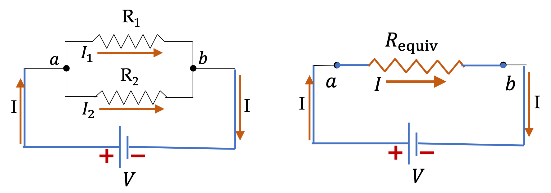
(b) The equivalent resistance across the source is the equivalent resistance of parallel resitors.
\begin{align*} R_\text{equiv} \amp = \left( \frac{1}{R_1} + \frac{1}{R_2} \right)^{-1} = \frac{R_1 R_2}{R_1 + R_2}\\ \amp = \frac{100\Omega \times 300\Omega }{100\Omega + 300\Omega } = 75\ \Omega. \end{align*}
Solution 3. (c)
(c) The equivalent resistance across the source is the equivalent resistance of parallel resitors.
\begin{align*} I \amp = \frac{V}{R_\text{parallel}} = \frac{20\text{ V}}{75\ \Omega} = 267\text{ mA} \end{align*}
Solution 4. (d)
(d) Using the results of (a) and (c) we get
\begin{align*} I_1 \amp = \frac{3}{4} I = 67\text{ mA}.\\ I_2 \amp = \frac{1}{4} I = 200\text{ mA}. \end{align*}

Exercises 34.7.4 Exercises

1. A Circuit with Three Resistors in Parallel.

Find the voltages \(V_1\text{,}\) \(V_2\) and \(V_3\) across individual resistors, the currents \(I_1\text{,}\) \(I_2\) and \(I_3\) through each resistor in the circuit for the following values of resistors and voltage. (a) \(R_1 = 2 \Omega\text{,}\) \(R_2 = 3 \Omega\text{,}\) \(R_3 = 4 \Omega\text{,}\) \(V=12\text{ V}\text{;}\) (b) \(R_1 = 10 \Omega\text{,}\) \(R_2 = 20 \Omega\text{,}\) \(R_3 = 30 \Omega\text{,}\) \(V=100\text{ V}\text{.}\)
Figure 34.39.
Answer.
(a) \(I_1 = 6 \ \text{A}\text{,}\) \(I_2 = 4 \ \text{A}\text{,}\) \(I_3 = 3 \ \text{A}\text{;}\) (b) \(I_1 = 10 \ \text{A}\text{,}\) \(I_2 = 5 \ \text{A}\text{,}\) \(I_3 = 10/3 \ \text{A}\text{.}\)
Solution 1. a
The resistors are in parallel and same voltage drops across each resistor.
\begin{equation*} V_1 = V_2 = V_3 = 12\;\text{V}. \end{equation*}
Hence, the current through each resistor is easily obtained using Ohm’s law for each.
\begin{align*} \amp I_1 = V_1/R_1 = 12\;\text{V}/2\:\Omega = 6\:\text{A},\\ \amp I_2 = V_2/R_2 = 12\;\text{V}/3\:\Omega = 4\:\text{A},\\ \amp I_3 = V_3/R_3 = 12\;\text{V}/4\:\Omega = 3\:\text{A}. \end{align*}
Solution 2. b
For the new values we get
\begin{equation*} V_1 = V_2 = V_3 = 100\;\text{V}. \end{equation*}
Therefore,
\begin{align*} \amp I_1 = V_1/R_1 = 100\;\text{V}/10\:\Omega = 10\:\text{A},\\ \amp I_2 = V_2/R_2 = 100\;\text{V}/20\:\Omega = 5\:\text{A},\\ \amp I_3 = V_3/R_3 = 100\;\text{V}/30\:\Omega = \frac{10}{3}\:\text{A}. \end{align*}

2. A Parallel Circuit of Three Resistors in Disguise.

Find current through each resistor in the circuit given in Figure 34.40.
Figure 34.40.
Hint.
Think of potential difference across each resistor.
Answer.
\(\frac{1}{10}\text{ A},\ \frac{1}{20}\text{ A},\ \frac{1}{30}\text{ A}\)
Solution.
As before, we will choose the negative terminal of the battery as zero potential reference. Then, the positive terminal of battery is at 10 volts. We see from the diagram in Figure 34.41 that the voltage situation across each of the resistors is same: Each resistor is actually connected across the two terminals of the battery.
Figure 34.41. This diagram shows that one side of each resitor is connected to the negative of the voltage source while the other side is connected to the positive. That means current from voltage source will split into three branches which will then combine. Thus, the three resitors are actually in parallel, even though the diagram does not have then drawn in a traditional parallel diagram.
The given circuit is identical with the three resistors connected parallel to the battery. Hence the currents are
\begin{align*} I_1 \amp = \frac{10\text{ V}} {100\ \Omega} = \frac{1}{10}\text{ A}.\\ I_2 \amp = \frac{10\text{ V}}{200\ \Omega} = \frac{1}{20}\text{ A}.\\ I_3 \amp = \frac{10\text{ V}}{300\ \Omega} = \frac{1}{30}\text{ A}. \end{align*}