   
Logo image

Physics Bootcamp

Section 6.2 Forces as Vectors

Subsection 6.2.1 Resultant Force

Force is a vector quantity since it has both magnitude and direction. The effect of a force on the motion of an object is independent of which body applies the force. For instance, an identical motion results from a force by someone pushing on a box or an equal force applied by a machine pulling on the box Figure 6.11.
Figure 6.11. Push or pull cause same motion.
Therefore, when several bodies exert forces on one object, the net effect of all forces is identical to one force that is a vector sum of all forces on the body. The net force is also called the resultant force.
If two forces acting on a body are parallel to each other, then the resultant force has a magnitude equal to the sum of the magnitudes of the two forces. If two anti-parallel forces act on an object, then the resultant force has a magnitude equal to the difference of the magnitudes of the two forces, and the direction of the larger of the two forces. If two forces act at an angle, then you need to use the parallelogram law of addition of vectors to figure out the resultant force. Often, it is much easier to work analytically with components of forces as we will see in worked out examples.

Example 6.12. Resultant force.

A box is pulled by a force of \(40\) N in the horizontal direction and a force of \(30\) N also horizontally but at an angle of \(90^{\circ}\) to the direction of the other force. Find the magnitude and direction of the resultant force.
Solution.
This problem can be done in a number of ways. Here we will illustrate two most commonly used methods
  1. Geometrical method. Place the second force at the tip of the first force as in Figure 6.13. Then the force from the tail of the first force to the tip of the second force is the resultant force. In the graphical method of addition, we use deduce the magnitude of the force by a scale for the drawing and use protractor to read off the angle. The scale on the drawing gives the magnitude of the force to be \(50\) N. A protractor gives the approximate angle of \(35^{\circ}\) vector \(\vec F\) makes with the horizontal direction. Note that it is impossible to read the angle with \(100\%\) precision and we will obtain only an approximate value for the angle when using the graphical method.
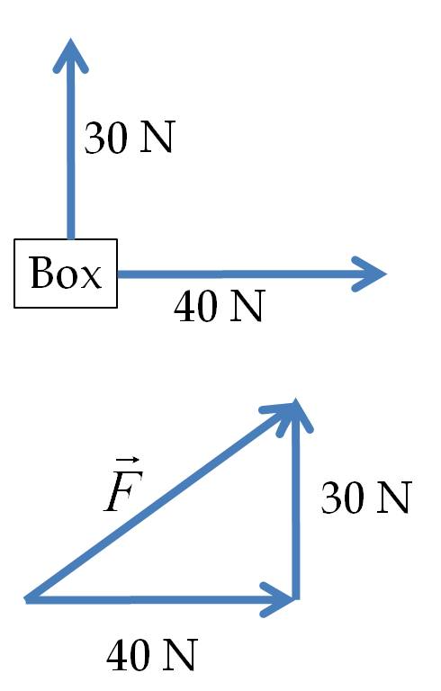
    Figure 6.13. Graphical addition of forces.
  2. Analytical Method.
    First, we choose Cartesian axes and figure out the Cartesian components of the given forces. The components are easy to figure out if you place origin of the coordinate system at the tails of the forces as shown inFigure 6.14. Then, we add the \(x\) components of the forces separately from their \(y\) and \(z\)-components to obtain the \(x\text{,}\) \(y\) and \(z\)-components of the resultant force.
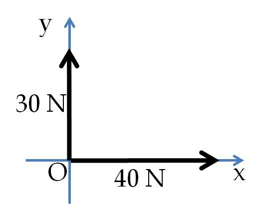
    Figure 6.14.
    The magnitude and direction of the resultant force are then calculated from its Cartesian components. In the present situation, we have the \(z\)-components all zero since the given forces fall in one plane. Therefore, we have only the \(x\) and \(y\)-components to work with. A table usually helps in organizing these calculations as shown below.
    Force \(x\)-comp (N) \(y\)-comp (N) \(z\)-comp (N)
    \(\vec F_1\) 40 0 0
    \(\vec F_2\) 0 30 0
    Resultant, \(\vec F\) 40 30 0
    Therefore, the magnitude of the force is
    \begin{equation*} F = \sqrt{F_x^2+F_y^2}=\sqrt{40^2+30^2} = 50\ \textrm{N}, \end{equation*}
    and the direction given as the angle from the positive \(x\)-axis is
    \begin{equation*} \theta =\arctan\left(\frac{F_y}{F_x}\right)=\arctan\left(\frac{30}{40}\right) = 37^{\circ}, \end{equation*}
    which is in general agreement with the result from the geometrical method given (a) above. It is clear that the geometrical approach gives the sum vector directly, while if you follow the analytic approach, you will get components from which you need to construct the magnitude and direction. Most of the time we will work using the analytic approach since it is usually easier to do and does not require us to draw vectors to scale.

Subsection 6.2.2 Component of a Force in a Given Direction

The magnitude of the component of a force in a given direction tells us the effect of force on the motion in that direction.
Geometrically: To obtain geometrically the component of a force in a given direction, we draw a projection of the force on a line in that direction. The length of the projection is equal to the component of the force in the given direction.
Analytically: Let direction of interest have a unit vector \(\hat u\) in that direction. The unit vector \(\hat u\) may be \(\hat u_x\text{,}\) \(\hat u_y\text{,}\) \(\hat u_z\text{,}\) or some other unit vector. The component of force \(\vec F\) in the direction of \(\hat u\) is given by the dot product of \(\vec F\) and the unit vector \(\hat u\text{.}\)
\begin{equation*} \textrm{The component of }\vec F \textrm{ in the direction of } \hat u = \vec F\cdot\hat u. \end{equation*}

Example 6.15. Component of Weight Along an Incline.

The weight of an object of mass \(m\) has magnitude \(W=mg\) and direction towards the center of Earth. The direction locally can be drawn vertically down. A cart of mass \(m\) is placed on an incline as shown in Figure 6.16. What is the component of weight vector along the incline?
Figure 6.16. A cart on an inclined plane. The component of weight parallel to the inclined plane \(ab\) is equal to \(OQ\) with \(OQ/OP = bc/ab\text{.}\)
Solution 1. Geometrical
We will show the calculation both geometrically and analytically.
Geometrical approach: We seek the component of weight parallel to the inclined plane (Figure 6.16). The weight \(W\) of the cart is pointed downward and is represented by arrow \(\overrightarrow{OP}\) with length \(OP = W\text{.}\) The projection of \(\overrightarrow{OP}\) on line \(ab\) is the component of weight parallel to the inclined plane. By drawing the projection, we see that the length \(OQ\) is equal to the component of weight we seek.
How do we find the length of \(OQ\) in terms of the known length \(OP\text{?}\) We can find the ratio \(OQ/OP\) by looking at similar triangles \(\triangle POQ\) and \(\triangle abc\text{.}\) Alternately we can use trigonometry. First, let us work out the similar triangle method. The triangles \(\triangle POQ\) and \(\triangle abc\) are similar triangles since \(\angle POQ = \angle abc\text{,}\) \(\angle PQO = \angle acb\text{,}\) and \(\angle OPQ = \angle bac\text{.}\) Therefore their sides are proportional also.
\begin{equation} \frac{OQ}{OP} = \frac{bc}{ab} = \sin\ \theta.\tag{6.1} \end{equation}
The effect of the weight on the motion of the cart is reduced by a factor of \(\sin\ \theta\text{,}\) where \(\theta\) is the inclination angle. To test this conclusion, we attach a spring balance to prevent the cart from sliding. The reading on the spring balance will be equal to the force given by \(OQ\text{,}\) i.e. \(W sin\ \theta\text{.}\)
We can use trigonometry also. The angle \(\angle QOP = 90^{\circ}-\theta\text{.}\) Therefore, in the right-angled triangle \(\triangle OPQ\text{,}\) the angle \(\angle OPQ = \theta\text{.}\) Using trigonometry of right-angle triangle we immediately find that
\begin{equation*} \sin\theta = \frac{OQ}{OP} \ \ \Longrightarrow\ \ OQ = OP\ \sin\theta, \end{equation*}
as found in Eq. (6.1).
Solution 2. Analytical
Analytic approach: We introduce a Cartesian coordinate system so that we can work out the components. Since we seek component along the incline, it makes sense to place one of the Cartesian axes along the incline as shown in Fig. \ref{fig:inclinedplane-weightcomponent-2}.
Figure 6.17. Axes for computing component of weight along incline.
Let the positive \(x\)-axis point down the incline, the positive \(y\)-axis normal to the incline, and the \(z\)-axis coming out of page. The weight vector is now not pointed along any of the axes. The vector is actually pointed in the fourth quadrant of the \(Oxy\) plane with angle \(\theta\) with respect to the negative \(y\)-axis, or \(90^{\circ}-\theta\) with respect to the positive \(x\)-axis. The \(x\)-component, \(W_x\) of the vector \(\vec W\) is therefore easily worked out to give
\begin{equation*} W_x = \vec W\cdot\hat u_x = W \cos(90^{\circ}-\theta) = W \sin\theta, \end{equation*}
which is same as what we found by the geometrical method.