   
Logo image

Physics Bootcamp

Section 38.5 Motional EMF from Rotation

If you do not have Calculus background, you can take the result of Eq. (38.18) below as given.
The changing magnetic flux as a result of the changing orientation of a loop is exploited to construct a source of current called the alternating current (AC) generator.
The orientation of a loop with respect to a magnetic field can be changed by rotating the loop. To rotate the loop one usually mounts the loop on a structure with a handle that can rotate the loop about an axis perpendicular to the direction of the magnetic field and to the area vector of the loop as shown in the figure. We will address later the question of how we connect the loop to the outside world to harness the energy in the induced current. For now, we focus our attention on how a current can be induced in a rotating loop.
Figure 38.32.
When the conducting loop is rotated at angular frequency \(\omega\) (rad/s), about an axis perpendicular to the the direction of magnetic field, the angle \(\theta\) between the area vector and the magnetic field will vary in time as
\begin{equation*} \theta(t) = \theta_0 + \omega t, \end{equation*}
where \(\theta_0\) is the starting angle at time \(t=0\text{.}\) To simplify the formulas we assume that the zero of time is the instant when the angle is zero. This gives
\begin{equation*} \theta(t) =\omega t. \end{equation*}
The area of the loop and magnetic field are kept constant so that magnetic flux through the area of the loop at time \(t\) is given by
\begin{equation*} \Phi_B = AB\cos\left(\omega t \right). \end{equation*}
If the closed circuit of the loop has \(N\) turns, then the open surface will have \(N\) such contributions to the magnetic flux. By the flux rule, the induced EMF \(\mathcal{E}\) would equal the negative of the rate of change of the magnetic flux,
\begin{equation} \mathcal{E}=-\frac{d\Phi_B}{dt} = \omega N A B \sin\left(\omega t \right).\tag{38.18} \end{equation}
This induced EMF is called rotational EMF and will induce current in the wires. In order for the current to come out of the rotating loop, the loop cannot be a closed wire but an open wire with which contacts have to be made from outside wires thus completing the loop for the current flow as shown in the diagram in Figure 38.33. The open loops are mounted on a drum, called the armature, which rotates about an axle. Slip rings are mounted on the axle to which outside wires make contact with the rotating open loops.
Figure 38.33. Main parts of an AC generator. As the loop is rotated, number of magnetic field lines passing through the surface of the loop changes, thus changing magnetic flux through the surface. In half the cycle flux increases and in other half the cycle the flux decreases, thus we get induced current alternating in direction. Such currents are called AC currents.
Let the resistance of the external device called load in Figure 38.33 be \(R_L\) before completing the loop and \(R_{\text{coil}}\) be the resistance of the rotating coil between the magnet poles. Then, the net resistance in the circuit will be
\begin{equation*} R_{\text{net}} = R_{\text{coil}} + R_L. \end{equation*}
In the completed circuit the net resistance is usually dominated by the resistance of the load. Therefore, the induced current in the circuit will be
\begin{equation} I_{\text{ind}} = \frac{\mathcal{E}}{R_{\text{net}}} \approx N\times \frac{\omega A B}{R_{L}}\sin\left(\omega t \right)\ \ (\text{with}\ R_L\gg R_{\text{coil}} ). \tag{38.19} \end{equation}
(Strictly speaking, this is not correct as we will find in subsequent chapters on dynamic circuits. You need impedance of the circuit to get current. We will ignore that complication here.)
The time dependence of induced current in this circuit is sinusoidal, and since the sine function reverses sign every half cycle, the sine of the current will change every half cycle. Therefore, the induced current will change direction every half cycle. This type of current is called alternating current (AC). The induced current has a peak value of \(N\omega A B/R\) in either direction.
\begin{equation} I_{\text{peak}} = N\omega A B/R_L. \tag{38.20} \end{equation}
The peak current in the coil is directly proportional to the number of turns in the coil, area of each loop of the coil, the strength of the magnetic field and the angular speed of rotation, and inversely proportional to the load resistance in the circuit. Thus, if you increase the number of turns by two, you would get twice as much induced current, assuming other quantities remain unchanged. If you rotate the loops twice as fast you would generate twice as big a current as illustrated in Figure 38.34.
Figure 38.34. Figure illustrates that as period is halved, i.e. as angular frequency is doubled, the peak induced current doubles.
The frequency of rotation of coils sets the frequency of the current in the circuit. In the late nineteenth century and early twentieth century, several different frequencies were in use. For instance, in 1918, there were ten different frequencies in use in London, England. The frequency of 50 Hz in Europe became more common due to the success of the German electric company AEG. In USA the enormous success of Westinghouse Electric led to the standard use of their 60 Hz by other suppliers.

Subsection 38.5.1 (Calculus) Energy Required for Rotation of Loop in Magnetic Field

Suppose, the net resistance of everything in the circuit is given by \(R\text{,}\) then the rate at which energy is dissipated in the circuit is given by the power dissipation formula for a resistor.
\begin{equation*} P(t) = I_{\text{ind}}(t)^2 R. \end{equation*}
Where does this energy come from? Note that the induced current in the rotating loop will have a torque \(\vec \tau_B\) from the magnetic field given by
\begin{equation*} \vec \tau_B = I_{\text{ind}}\vec A\times \vec B\ \ \text{(1-turn)} \end{equation*}
for a 1-turn loop. But, if the loop is rotated at a constant angular velocity, this torque must be balanced by a torque \(\vec \tau_{app}\) applied by an external agent as shown in Figure 38.35.
Figure 38.35. Rotational work is done by the external torque that balances the torque on the wires by magnetic field. During the interval \(t\) to \(t+dt\) the loop rotates by an angle \(d\theta\) which is not shown in the figure.
\begin{equation} \vec \tau_{appl} = - \vec \tau_B = -I_{\text{ind}}\vec A\times \vec B. \label{}\tag{38.21} \end{equation}
By the energy balance, we require that the rotational work done by the external agent must be equal to the total energy dissipated in the circuit. Using the current from Eq. (38.19) for \(N=1\) in Eq. (38.21) and doing the calculation for work for rotation from \(\theta=\omega t\) to \(\theta+d\theta = \omega(t+dt)\) we find
\begin{equation*} dW_{\text{rot}} = \frac{\omega A^2 B^2}{R}\sin^2\theta d\theta \end{equation*}
Replacing \(d\theta\) by \(\omega dt\) we get
\begin{equation*} dW_{\text{rot}} = \frac{\omega^2 A^2 B^2}{R}\sin^2(\omega t)dt. \end{equation*}
Integrating over one cycle we find the work done by the applied torque.
\begin{align*} W_{\text{one cycle}} \amp = \frac{\omega^2 A^2 B^2}{R}\int_0^{2\pi/\omega}\sin^2(\omega t)dt\\ \amp = \frac{1}{2}\frac{\omega^2 A^2 B^2}{R} T, \end{align*}
where \(T\) is period, \(T= 2\pi/\omega\text{.}\) This result can be written in terms of the peak current as
\begin{equation*} W = \frac{1}{2}I_{\text{peak}}^2 R T. \end{equation*}
We define a new measure of current, called the root-mean square (RMS) current, \(I_{\text{rms}}\) by
\begin{equation*} I_{\text{rms}} = \frac{I_{\text{peak}}}{\sqrt{2}}. \end{equation*}
With the rms-current, we can write the energy dissipated in each cycle by a formula that looks similar to the formula in a Direct Current (DC) circuit.
\begin{equation*} W = I_{\text{rms}}^2 R T. \end{equation*}
Dividing out the period we see that average power \(P_{\text{ave}}\) dissipated, averaged over full cycles, is given by
\begin{equation*} P_{\text{ave}} = I_{\text{rms}}^2 R. \end{equation*}
A good exercise for the student at this point would be work out the formulas for an \(N\)-turn rotating coil.

Example 38.36. Induced EMF in a Rotating Ring in a Magnetic Field.

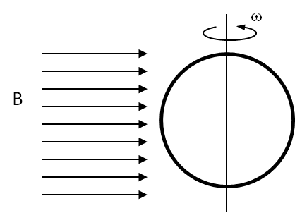
A circular loop of wire of radius \(10\, \text{cm}\) is mounted on a vertical shaft and rotated at a frequency of \(5\) cycles per second in a region of uniform magnetic of \(2\, \text{G}\) perpendicular the axis of rotation. (a) Find an expression for the time-dependent flux through the ring. (b) Determine the time-dependent current through the ring if it has a resistance of \(10\,\Omega\text{.}\)
Answer.
(b) \(1.97\times 10^{-5}\sin(10\pi t) \ \textrm{A}\)
Solution 1. (a)
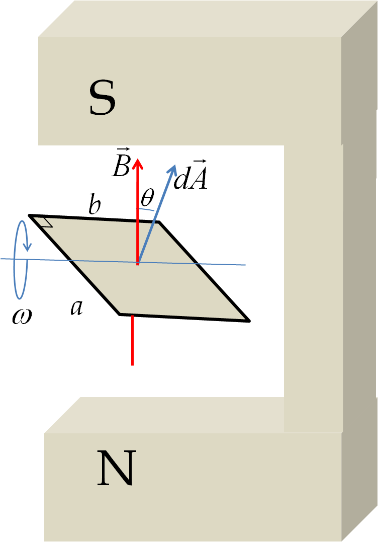
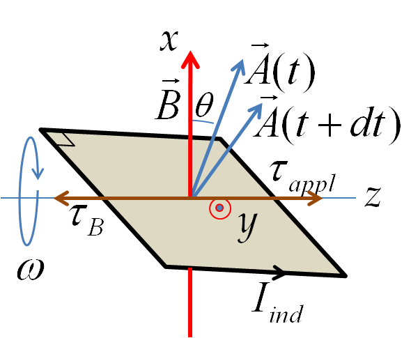
Let the axis of the rotation of the ring be along the \(z\)-axis and let the horizontal direction in the figure be the \(x\)-axis. Then we need the projection of normal to the area on the \(x\)-axis for computing the flux through the loop of the ring. Let \(\theta\) be the angle that the normal to the area makes with the \(x\)-axis. Suppose the ring is oriented so that \(\theta =0\) at \(t=0\text{.}\) Then, \(\theta\) at an arbitrary time \(t\) will be
\begin{equation*} \theta(t) = \omega\: t. \end{equation*}
Therefore, the magnetic flux through the loop at this instant will be
\begin{equation*} \Phi = B\:A\:\cos\theta(t). \end{equation*}
Solution 2. (b)
The induced EMF in the ring is equal to the rate of change of flux.
\begin{equation*} \mathcal{E} = \left|\dfrac{d\Phi}{dt} \right| = \omega\:B\:A\:\sin\theta(t) \end{equation*}
The magnitude of the induced current in the ring is obtained by dividing the induced EMF by the resistance of the ring.
\begin{align*} 
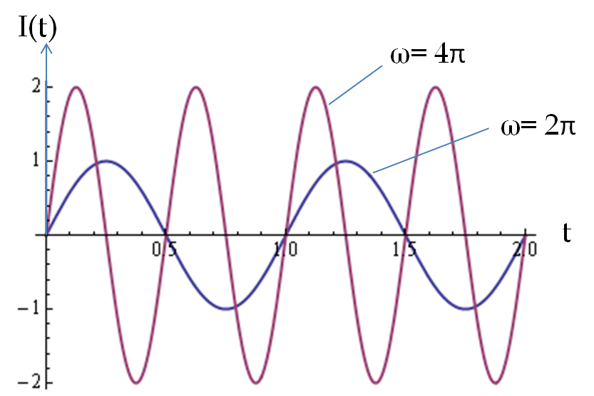
I \amp = \dfrac{\mathcal{E}}{R} = \dfrac{\omega\:B\:A\:|\sin\theta(t)|}{R}\\ \amp = \dfrac{2\pi\times 5\:\textrm{Hz}\times 2\times 10^{-4}\:\textrm{T}\times \pi\:(0.1\:\textrm{m})^2}{10\:\Omega} \\ \amp = 1.97\times 10^{-5}|\sin(10\pi\:t)|\: \textrm{Amp}. \end{align*}