   
Logo image

Physics Bootcamp

Section 43.8 Bending of Light at Plane Interface

In this section we will explore consequences of reflection and refraction of light a little further. We will focus here on plane interface only. In the next chapter we will look at curved interfaces.

Subsection 43.8.1 Total Internal Reflection and Critical Angle

You saw in Figure 43.23 that if \(n_2 \lt n_1\text{,}\) then the angle of refraction (\(\theta_2\)) is greater than the angle of incidence (\(\theta_1\)). But angle of refraction \(\theta_2\) cannot exceed \(90^\circ\) and the refracted ray be still in media \(n_2\text{.}\) That means that there is an angle of incidence (\(\theta_1 \lt 90^\circ\)) at which angle of refraction will be \(90^\circ\) as illustrated in Figure 43.26. This incidence angle is called critical angle. We will denote this angle by \(\theta_c\text{.}\)
\begin{equation*} n_1 \sin\theta_c = n_2 \sin 90^{\circ} \ \ \ (n_2 \lt n_1). \end{equation*}
This gives the following formula for the critical angle.
\begin{equation} \theta_c = \sin^{-1}\left(\frac{n_2}{n_1} \right).\tag{43.26} \end{equation}
Figure 43.26. Critical angle and total internal reflection. Ray 3 corresponds to the critical angle while ray 4 is totally internally reflected.
The rays of light that are incident on the interface at greater angle of incidence than the critical angle, i.e., when \(\theta_1 \ge \theta_c\text{,}\) will be reflected back in the \(n_1\)-medium as demonstrated in Figure 43.27. The phenomenon is called total internal reflection. The concepts of critical angle and total internal reflection find their use in Fiber optics as explained next.
Figure 43.27. Total internal reflection demonstrated (MS). Rays from water incident on the horizontal water/air interface at (a) \(40^{\circ}\text{,}\) (b) \(49^{\circ}\) (infinitesimally larger than the critical angle) and (c) \(60^{\circ}\) at water/air interface are shown. For incident rays greater than critical angle, there are no refracted rays in air.

Example 43.28. Critical Angle at Air/Water Interface.

Find the critical angle for air/water interface.
Answer.
\(48.8^\circ\text{.}\)
Solution.
The critical angle lies in the medium of higher refractive index, here water, and has the following value.
\begin{equation*} \theta_c = \sin^{-1}\left(\frac{n_2}{n_1} \right) = \sin^{-1}\left(\frac{1.00}{1.33} \right) = 48.8^{\circ}. \end{equation*}

Subsection 43.8.2 Total Internal Reflections in Fiber Optics

Fiber optics makes use of the phenomena of total internal reflection to transmit light at great distances by using a dielectric optical fiber (Figure 43.29 and Figure 43.30). A thin layer of a transparent material of lower index of refraction, called cladding, is deposited on the surface of the fiber to prevent the leakage of light from one fiber to another in a bundle of fibers.
Figure 43.29. The fiber is made of a transparent material with a thin layer of a material of lower refractive index coated such that rays of light entering the fiber at appropriate angles are totally reflected back in the fiber.
When a ray of light traveling in the fiber strikes the fiber/cladding interface at an incidence angle greater than the critical angle \(\theta_c\text{,}\) it will be totally reflected back in the fiber. Therefore, there is a maximum angle \(\theta_{\text{max}}\) at which a ray must enter the fiber (point X) if it is to travel by total internal reflection. If the ray enters at a greater angle then the refracted ray XY inside the fiber will strike the fiber/cladding interface at less than the critical angle. This would lead to the leakage of light through the fiber/cladding interface.
We can find \(\theta_{\text{max}}\) as follows. Let \(n_f\) be the refractive index of fiber and \(n_c\) that of the cladding. From Snell’s law at the entry point X we have the following relation.
\begin{equation*} n_f\ \sin\theta_r = n_{\text{air}}\ \sin\theta_{\text{max}} \end{equation*}
From triangle XYZ we have
\begin{equation*} \theta_r = \frac{\pi}{2} -\theta_c. \end{equation*}
The critical angle for fiber/clad interface is given by
\begin{equation*} \sin\theta_c =\frac{n_c}{n_f}. \end{equation*}
From the last three equations, we find the following for \(\sin\theta_{\text{max}}\text{.}\)
\begin{equation*} n_{\text{air}}\,\sin\theta_{\text{max}} = \sqrt{n_f^2-n_c^2} \end{equation*}
The product \(n_{\text{air}}\sin\theta_{\text{max}}\) is called the numerical aperture or NA, which is a measure of the light gathering power of the fiber. Optical fibers are used in a number of applications - communication, e.g. transatlantic fiber cable, and medical imaging, e.g. various endoscopes to probe inside organs.
Figure 43.30. Picture of Laser light through an optical fiber.

Subsection 43.8.3 Bending of Light Through a Prism

You may be familiar with triangular piece of glass as prism, but a prism may have any shape.
In a triangular prism, a light ray incident on one face may emerge from any three of the faces after two or more refractions and reflections, and consequently the direction of light may be changed drastically as shown by angle of deviation \(\alpha\) in Figure 43.31.
Figure 43.31. Angle of deviation \(\alpha\) for a ray entering a triangular prism.
In the following example, I illustrate the calculation of the angle of deviation of a light ray passing through two faces of a prism.

Example 43.32. Deviation of Ray by a Prism.

Consider a ray of light incident on a right-angled triangular prism with a \(40^\circ\) angle at the base as shown in Figure 43.33. Let the angle of incidence be \(30^\circ\text{.}\) Find the angle of deviation assuming the index of refraction of glass and air for the given light to be \(1.5\) and \(1.0\) respectively.
Figure 43.33. Angle of deviation \(\alpha\) for a ray entering a triangular prism.
Answer.
\(29.6^\circ\text{.}\)
Solution.
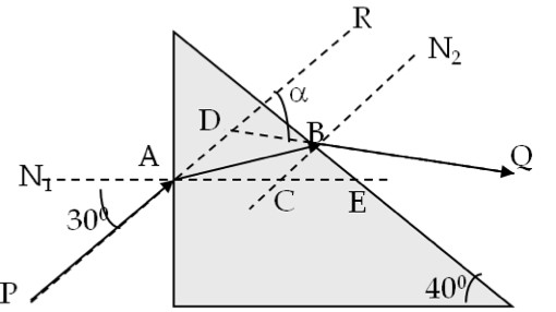
Using Snell’s law at A we obtain angle \(\angle\)BAC to be:
\begin{equation*} \angle\textrm{BAC} = \sin^{-1}\left(\frac{\sin 30^{\circ}}{1.5} \right) = 19.5^{\circ}. \end{equation*}
Since \(\triangle\text{BEC}\) in the right angled triangle \(\angle\text{BEC}\) is \(40^{\circ}\) because the side CE is parallel to the base, angle \(\angle\text{BCA}\) = \(90^{\circ}\) + \(40^{\circ}\) = \(130^{\circ}\text{.}\) In triangle \(\triangle\text{ACB}\text{,}\) angle \(\angle\text{ABC}\) = \(180^{\circ}\) - \(130^{\circ}\) - \(19.5^{\circ}\) = \(30.5^{\circ}\text{.}\) This is the angle of incidence at the second interface. Now applying Snell’s law at B, we obtain angle \(\angle\text{N}_2\text{BQ}\) to be:
\begin{equation*} \angle\textrm{N}_2\textrm{BQ} = \sin^{-1}\left(1.5\times \sin 30.5^{\circ}\right) = 49.6^{\circ} \end{equation*}
In rectangle ADBC, we know the following angles.
\begin{equation*} \angle \textrm{DAC} = 30^{\circ}, \ \angle \textrm{BCA} = 130^{\circ},\ \angle \textrm{CBD} = 49.6^{\circ}. \end{equation*}
Therefore, we find the angle \(\angle\text{ADB}\) to be
\begin{equation*} \angle \textrm{ADB} = 360^{\circ} - 30^{\circ} - 130^{\circ} - 49.6^{\circ} = 150.4^{\circ}. \end{equation*}
Hence the angle of deviation \(\angle\text{RDQ}\) is equal to \(180^{\circ} - 150.4^{\circ} = 29.6^{\circ}\text{.}\)

Exercises 43.8.4 Exercises

1. Deviation of a Ray Through an Equilateral Traingular Prism.

Find the angle of deviation of a ray through an equilateral triangular glass prism of refractive index \(1.55\) if the angle of incidence is \(70^\circ\text{.}\)
Hint.
Draw rays and work on each refraction using Snell’s law.
Answer.
\(46.7^{\circ}\text{.}\)
Solution.
In this exercise, we will work out various angles using Snell’s law. Refer to Figure 43.34 as we work through calculations below.
Figure 43.34. Figure for Exercise 43.8.4.1.
The angle of refraction at the incident face will be
\begin{equation*} \theta = \sin^{-1}\left( \dfrac{1\times \sin\:70^{\circ}}{1.55}\right) = 37.3^{\circ}. \end{equation*}
We draw this ray at B which strikes the other face at C. See completed figure below. The ray BC is the incident ray at C. Using the angles of the triangle \(\triangle\text{ABC}\) we see that the incident angle in glass at C is \(22.7^\circ\text{.}\) Now, we apply Snell’s law at point C to find the angle with which the ray exits the prism.
\begin{equation*} \theta = \sin^{-1}\left( \dfrac{1.55\times \sin\:22.7^{\circ}}{1}\right) = 36.7^{\circ}. \end{equation*}
Now, from the triangle \(\triangle\text{BCE}\) we find that the angle \(\angle\text{BEC}\) \(=\) \(180^\circ- 37.3^\circ-22.7^\circ\) \(= 120^\circ\text{.}\) From quadrilateral BDCE we get
\begin{equation*} 180^{\circ} - \phi = 360^{\circ} - 70^{\circ} - 36.7^{\circ} - 120^{\circ} = 133.3^{\circ}. \end{equation*}
Therefore, the angle of deviation of the incident ray will be
\begin{equation*} \phi = 180^{\circ} - 133.3^{\circ} = 46.7^{\circ}. \end{equation*}

2. Tracing Ray in a Triangular Prism.

Use Snell’s law and a protractor to find the direction of a \(700\text{-nm}\) wavelength light passing through a triangular prism made of flint glass shown in the figure below. Use \(n=1.62\) for the refractive index of the flint glass.
Figure 43.35. Figure for Exercise 43.8.4.2.
Hint.
Find angle of refraction at left surface of the prism and draw the ray inside glass. Read the angle of incidence of this ray inside the glass at the right surface, and calculate the refraction angle into air at that face.

3. Ray Through a Right-angled Prism.

A plastic plate as shown in Figure 43.36 is immersed in oil. Find the incident angle so that the ray comes out vertically from the base of the plate. (Use \(n = 1.6\) for plastic and \(n = 1.3\) for oil.)
Figure 43.36.
Hint.
Start from the exiting ray and work backwards.

4. Ray Through a Hexagonal Prism.

A yellow light of wavelength \(589\, \text{nm}\) in air is incident on a flint-glass hexagonal prism as shown in Figure 43.37. Find the path of the ray through the prism and determine the edge(s) the light will come out if the refractive index of glass is \(1.58\text{.}\) If the ray suffers multiple reflections within the glass, trace rays that have at least two reflections.
Figure 43.37.

5. Converging Lens from Two Triangular Prisms.

A student puts together two equilateral triangular prisms as shown in Figure 43.38. He claims that the prism will converge rays just like a converging lens. Find the paths of the two rays through the prisms to decide if he is right.
Figure 43.38.