52.Kinematics of a Round Penny Rolling Uniformly in a Circular Groove.
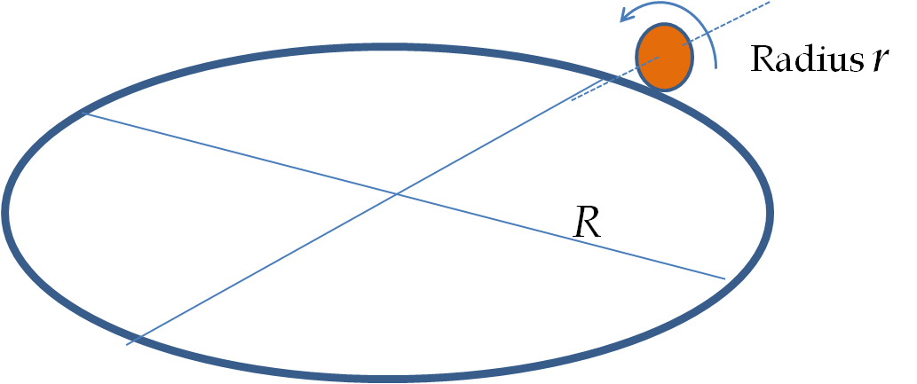
A circular groove of diameter \(50\) cm is made in a horizontal table. A penny (diameter \(1\) cm) is rolled in the groove. Suppose, the penny rolls at right angle without slipping. (a) Find the total angle the penny rotates about an axis through the center as it goes around the groove once. (b) When the penny rotates at a steady rate, and it takes 10 sec to go around the circle. What is its instantaneous rotation velocity of the penny? (c) Going around the circle can be considered as a revolution of the CM of the penny about an axis that goes through the point of the circle that is momentarily in contact with the groove. What is the angular velocity vector of the CM about this axis?
In each turn the penny goes a distance \(2\pi r\text{.}\) Let \(n\) be the number of turns that the penny makes when going all the way around, which would be a distance of \(2\pi R\text{.}\)
\begin{equation*}
(n)(2\pi r) = 2\pi R.
\end{equation*}
Figure9.141.
Note that \(n\) can be any positive real number and not be restricted to integers only. Solving for \(n\) we get
\begin{equation*}
n = \frac{R}{r} = \frac{50\ \textrm{cm}}{1\ \textrm{cm}} =50.
\end{equation*}
Therefore, the total angle rotated = \(50\times 2\pi = 100\pi\ \textrm{rad}\text{.}\)
Solution2.b
The penny rotates \(100\pi\ \textrm{rad}\) in 10 sec. Therefore, the angular speed of the penny will be \(100\pi /10 = 10\pi\) rad/sec. This rotation is about an axis through the center of the penny and perpendicular to the flat surface of the penny. The direction of the angular velocity will be changing since the axis of rotation of the penny changes direction with time.
Solution3.c
The motion of the CM about an axis through the center of the circle of the track and perpendicular to the circle of the track is also a rotation, called the revolution of the penny in the track. This motion is analogous to the motion of the Earth around the Sun. The angular speed of this revolution is obtained by dividing the total angle in one circle by the time of 10 sec to completely go around the circle. This gives \(2\pi/10 = \pi/5\) rad/sec.
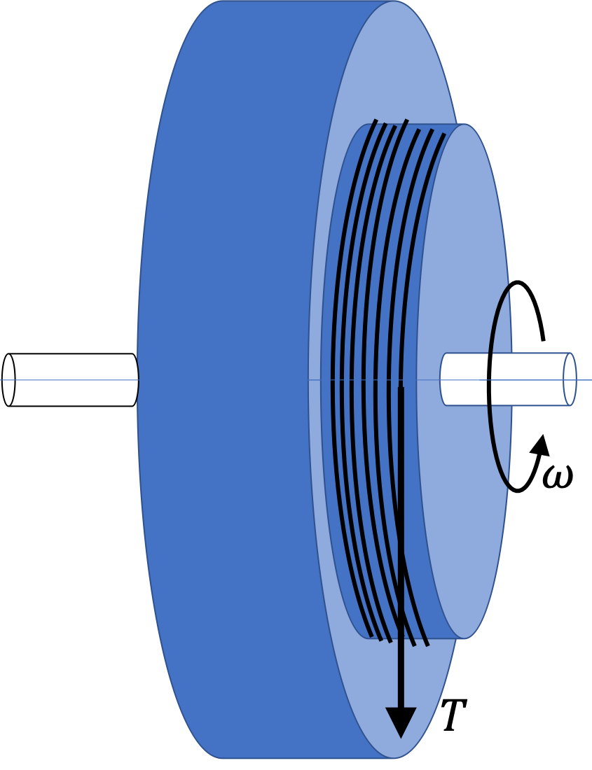
53.Unwinding Rope on a Wheel.
A wheel of mass \(M\) and radius \(R\) is mounted vertically on an axle of radius \(r\text{.}\) A light rope is wound on the wheel. When the rope is pulled, it unwinds at a distance \(\dfrac{2}{3} R\) from the center of the wheel without slipping as shown.
Figure9.142.
(a) Suppose the tension in the rope has a magnitude \(T\) at some instant in time, what will be the angular acceleration of the wheel at that instant if the effects of friction at the axle can be neglected?
(b) Suppose you find that a tension of magnitude \(T_0\) is needed to pull the string at a constant speed, what friction must be acting at the axle if friction acts at a distance \(r\) from the center of the wheel?
Hint1.(a)
(a) The lever arm of \(T\) is \(\dfrac{2}{3} R\text{.}\)
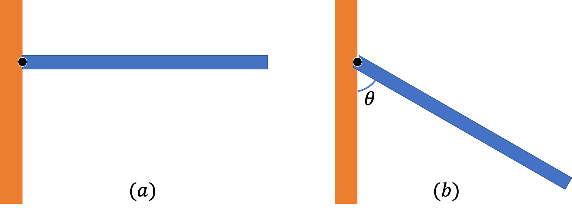
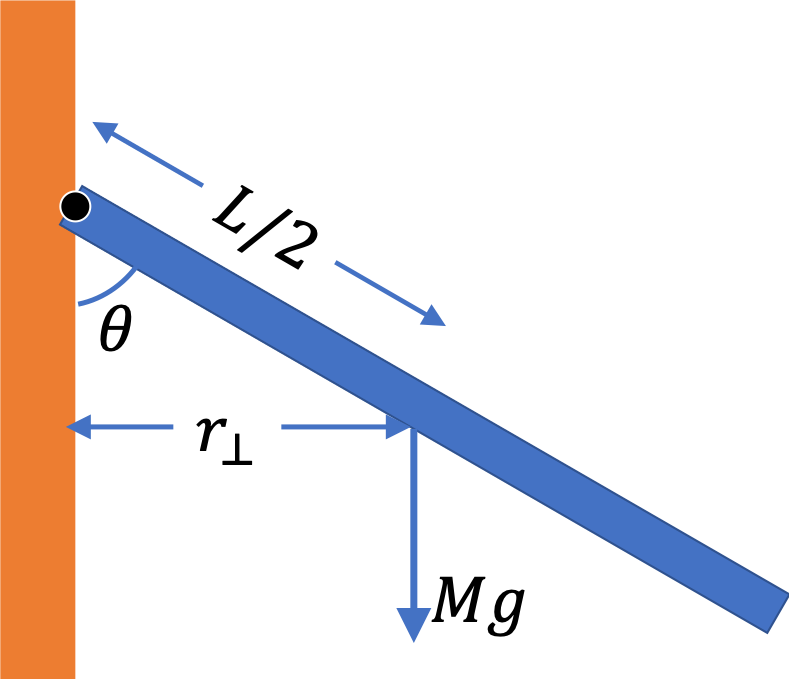
54.Angular Acceleration of a Falling Plank Hinged at One End.
A plank of mass \(M\) and length \(L\) is hinged at one end. Initially, the plank is supported at the free end so that the plank is horizontal. When the plank is released, the imbalance of the torque on the plank causes a varying angular acceleration of the plank.
Figure9.143.
(a) Find the angular acceleration of the plank at two instants immediately after the plank is released.
(b) Find the angular acceleration of the plank when the plank makes an angle \(\theta\) with the horizontal.
Hint.
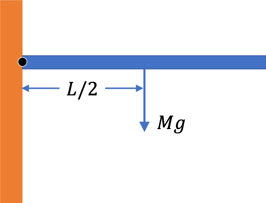
(a) Weight acts at the center, (b) Figure out the lever arm of weight when the plank makes an angle \(\theta\text{.}\)
Only weight acts at points away from the pivot. We can place the entire weight at the center of the plank. This gives the torque by weight \(MgL/2\text{.}\) Since the plank rotates about an axis through one end, we wil luse the formula of moment of inertia for a rod with axis at the end. These give
\begin{equation*}
I\alpha = \dfrac{M g L}{2},\ \ \ I = \dfrac{1}{3}\,ML^2.
\end{equation*}
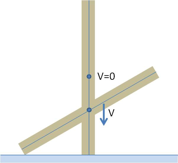
55.(Calculus) Meter Stick Sliding on a Table from Vertical to Horizontal Orientation.
A meter-stick is set almost vertically on a frictionless table. When the stick is let go at rest from the nearly vertical orientation it falls to the table. Since there is no horizontal force on the stick and it starts out at rest, the center of mass of the stick falls straight down. Find the speed of the CM as a function of the position of the CM with respect to the table. Hint:
Figure9.146.
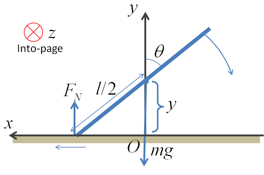
Let the \(y\)-axis be the vertical direction and the \(z\)-axis into-the-page, and write the \(y\)-component of equation of motion for the translation of CM and the \(z\)-component of the rotational motion of the stick about the CM.
Numerical: when it has fallen a vertical distance of \(10\text{ cm}\text{,}\) answer is \(1.01\text{ m/s}\text{.}\)
Hint.
Use energy conservation with energy when vertical to when at an angle.
Answer.
\(- \left[\frac{3g l (1-\cos\theta)}{3+ \textrm{cosec}^2\theta} \right]^{1/2}\ \hat j\text{.}\)
Solution.
Since there is no horizontal force on the stick and since the CM of the stick does not have any initial velocity in the horizontal direction, the CM will fall vertically down. As the stick falls down, the lower part of the stick will move one way and the upper part the other way. The rotational motion of the stick about an axis through the CM is possible due to the normal force from the table. For concreteness we will point the positive \(y\)-axis up and measure the angle of rotation with respect to the vertical as shown in Figure 9.147.
The relation between the \(y\)-coordinate of the CM and the angle \(\theta\) is
\begin{equation*}
y = \frac{l}{2} \cos\theta.
\end{equation*}
The time derivative \(y\) will give the \(y\)-component velocity and the time derivative of \(\theta\) will give the \(z\)-component of the angular velocity.
Here the choice of the angle gives \(d\theta/dt\) positive since \(\theta\) will increase with time. As the \(y\)-coordinate of the CM is decreasing with time we expect the \(y\)-component of the velocity to be negative, i.e. the velocity pointed towards the negative \(y\)-axis.
Now, we use the energy conservation between the initial time \(t=0\) and at an arbitrary time \(t=t\text{.}\) The reference of the potential energy will be take to be zero when the CM of the stick is on the table. The CM is initially at \(y=l/2\) and the stick is at rest. The CM at an arbitrary time is at \(y=y\text{,}\) and the CM is translating with speed \(|dy/dt|\) and the stick is rotating about an axis through the CM parallel to the \(z\)-axis in the figure with the angular speed \(|d\theta/dt|\text{.}\) Therefore,
\begin{equation*}
\frac{1}{2} m \left( \frac{dy}{dt}\right)^2 + \frac{1}{2} I_0 \left( \frac{d\theta}{dt}\right)^2 + m g y = m g \frac{l}{2},
\end{equation*}
where
\begin{equation*}
I_0 = \frac{1}{12} m l^2.
\end{equation*}
Now, using Eq. (9.124) we can write the speeds in terms of \(|dy/dt|\) and solve for \(|dy/dt|\text{.}\)
\begin{equation}
\left( \frac{dy}{dt}\right)^2 = \frac{3g l (1-\cos\theta)}{3+ \textrm{cosec}^2\theta}.\tag{9.125}
\end{equation}
Therefore, the velocity of the CM is
\begin{equation*}
\vec v = \frac{dy}{dt} \hat j = - \left[\frac{3g l (1-\cos\theta)}{3+ \textrm{cosec}^2\theta} \right]^{1/2}\ \hat j,
\end{equation*}
where I have used the negative root in Eq. (9.125) to agree with the motion down as shown in the figure.
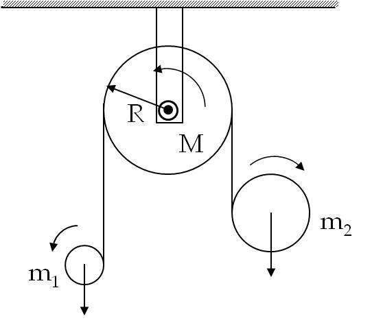
56.Tape Unwounding on Two Disks with Tape Going Over a Pulley.
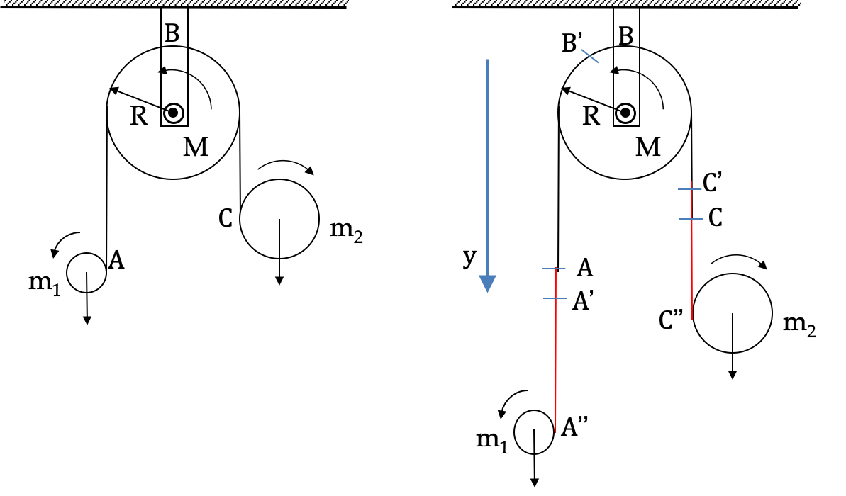
A “massless” tape is wound on one disk of mass \(m_1\) and radius \(R_1\text{.}\) The tape then goes over a pulley of mass \(M\) and radius \(R\) and the other end of the tape is wound on another disk of mass \(m_2\) and radius \(R_2\) as shown in Figure 9.148. The disks are then released from rest with tapes taut on each side. Assume the tape unwinds smoothly on each side. Determine the accelerations of each mass and the angular acceleration of the pulley.
To work out the relations among accelerations, we notice that tape unwinds smotthly on the pulley and does not slide over it. That would mean, the accelerations of the disks will come from both unwindind of their tapes and the spinning of the pulley.
Point \(y\) axis down and denote \(y\) acceleration components of the disks by \(a_1\) and \(a_2\text{,}\) and angular acceleration magnitudes by \(\alpha_1\) and \(\alpha_2\) of the disks and \(\alpha\) of the pulley. Looking at two instants, in the motion as shown in Figure 9.149. The rotation of the pulley adds AA’=BB’ to disk 1 and subtracts CC’=BB’. In addition unwinding of tape adds A’A" to disk 1 and C’C" to disk2. Therefore, the accelerations are related as follows.
\begin{align}
a_1 \amp = R_1\alpha_1 + R \alpha, \tag{9.126}\\
a_2 \amp = R_2\alpha_2 - R \alpha. \tag{9.127}
\end{align}
We solve Eqs. (9.126)-(9.132) simultaneously for seven unknowns, \(T_1,\ T_2,\ a_1,\ a_2,\ \alpha_1,\ \alpha_2,\ \alpha\text{.}\) I will illustrate elimintation steps to \(\alpha\) only. You can fill in the work for the others.
First elimintate \(a_1\) and \(a_2\) from Eqs. (9.128) and (9.129) using the constraint equations Eqs. (9.126) and (9.127).
\begin{align}
\amp m_1R_1\alpha_1 + m_1 R \alpha = m_1 g - T_1, \tag{9.133}\\
\amp m_2R_2\alpha_2 - m_2 R \alpha = m_2 g - T_2. \tag{9.134}
\end{align}
Now, using Eqs. (9.130) and (9.131), we eliminate \(T_1\) and \(T_2\) from Eqs. (9.133), (9.134), and (9.132). We end up with three equations in \(\alpha_1\text{,}\)\(\alpha_2\text{,}\) and \(\alpha\text{.}\)
\begin{align}
\amp \frac{3}{2} m_1R_1\alpha_1 + m_1 R \alpha = m_1 g, \tag{9.135}\\
\amp \frac{3}{2} m_2R_2\alpha_2 - m_2 R \alpha = m_2 g. \tag{9.136}\\
\amp m_1R_1\alpha_1 -m_2R_2\alpha_2 - M R \alpha = 0. \tag{9.137}
\end{align}
Using first of these for \(m_1R_1\alpha_1\) and second for \(m_2R_2\alpha_2\) in the third equation leads to \(\alpha\) of the pulley.
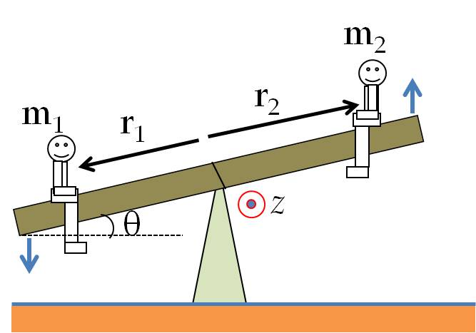
This is a long problem and covers a number of important concepts. Two children of mass \(m_1\) and \(m_2\) are sitting at \(r_1\) and \(r_2\) from the center on the two sides of a plank of mass \(M\) and length \(L\) that is pivoted at the center as shown in Figure 9.150. Consider a particular instant when the plank makes an angle \(\theta\) with the horizontal direction and is rotating counterclockwise. Let the origin of Cartesian coordinate system be at the pivot point, which is the point where the plank touches the support, the \(z\)-axis be perpendicular to the drawing shown in Figure 9.150, and the positive \(z\) direction corresponds to the ``coming out-of-page’’ direction.
Figure9.150.
Assume there is enough static friction between the children and the plank so that the children do not slide on the plank.
Draw free-body diagrams of the forces on each child, choose a coordinate system, and write Newton’s second law equations for the two children in the component form.
Draw a diagram showing all forces on the plank and where they act, choose a coordinate system with origin at the pivot point, and find the components of the net torque on the plank about the pivot point.
Draw a free-body diagram of the forces on the plank, and determine the components of the net force on the plank.
Write rotational equation of motion for the plank in the component form. Note that the force by children on the plank will not be \(mg\) of the children but the normal and frictional forces between the children and the plank. Note: the force \(mg\) on a child acts on that child, not on the plank. The force between the plank and the child consists of normal and frictional forces between the two.
Write any relations between components of the acceleration and the angular acceleration of the plank.
Solve the equations you have generated for (i) acceleration of the children at the instant under consideration, (ii) the angular acceleration of the plank, (iii) the forces between the children and the plank, and (iv) the force of the support on the plank at the pivot point.
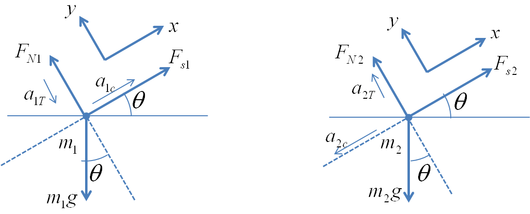
Solution1.a
Figure 9.151 below show the free-body diagrams. Each child has three forces, the weight \(mg\text{,}\) the normal \(F_N\text{,}\) and the static frictional force \(F_s\text{.}\) Note \(F_s\) is not necessarily \(\mu_s F_N\) since the static friction force may not be the maximum.
Figure9.151.
The children also have a non-zero acceleration. It is a common mistake to treat the acceleration of the children as having a zero value. If the plank has an angular acceleration, then the children will also have a tangential acceleration since they will be accelerating in the circle of their motion.
Since the entire system has the same angular acceleration, the magnitudes of the tangential accelerations of the two children can be expressed in terms of the magnitude \(\alpha\) of the angular acceleration as
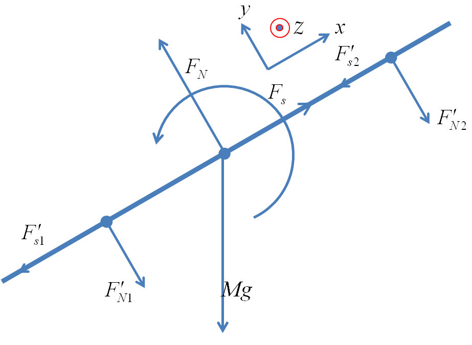
The figure below shows forces on the plank. The normal force and the friction between the children are labelled with a prime - they have the same magnitude as the corresponding forces on the children but when they act on the plank their directions are opposite to when they act on the children.
Figure9.152.
The \(z\)-component of the rotational equation of motion of the plank will be
Similarly for the other child. From these expressions we can compute the magnitude and direction the accelerations in the usual way.
(iii) The net force on any child from the plank has two components, the normal and the friction. The friction is along the \(x\)-axis and gives the \(x\)-component of this net force and the normal is along the \(y\)-axis and gives the \(y\)-component of the force. It is left as an exercise for the student to complete the task.
(iv) The force of the support on the plank has two components \(F_N\) and \(F_s\text{,}\) which can be coputed by using Eqs. (9.143) and (9.144).