Logo image

Physics Bootcamp

Section 36.6 Magnetic Field Bootcamp

Exercises Exercises

Magnetic Field of Steady Current

1. Magnetic Field of a Long Straight Wire Carrying Current.
Follow the link: Example 36.4.
2. Magnetic Field at Various Distances from a Long Wire Carrying Current.
Follow the link: Example 36.5.
3. Magnetic Field of two Parallel Wires Carrying Current.
Follow the link: Example 36.6.
4. Force Between Oppositely Directed Currents.
Follow the link: Example 36.8.
5. Comparing Magnetic Field of Current in Wire to that of Earth.
Follow the link: Exercise 36.1.3.1.
6. (Calculus) Magnetic Field at Symmetric Point from Current in a Finite Straight Wire.
Follow the link: Example 36.11.
7. (Calculus) Magnetic Field at Arbitry Point from Current in a Finite Straight Wire.
Follow the link: Example 36.13.
8. (Calculus) Magnetic Field of Current in Infinitely Long Wire by Biot-Savart Law.
Follow the link: Example 36.15.
9. (Calculus) Magnetic Field on the Symmetry Axis of a Circular Loop.
Follow the link: Example 36.16.
10. (Calculus) Magnetic Field at Center of a Wire Bent into a Square.
Follow the link: Exercise 36.1.3.2.
11. (Calculus) Magnetic Field Near the End of a Circular Hairpin.
Follow the link: Exercise 36.1.3.3.
12. Magnetic Field of Current in a Finite Wire by Biot Savart Law Ex1.
Follow the link: Exercise 36.1.3.4.
13. Magnetic Field of Current in a Finite Wire by Biot Savart Law Ex2.
Follow the link: Exercise 36.1.3.5.
14. Magnetic Field of Current in a Rectangulat Wire by Biot Savart Law.
Follow the link: Exercise 36.1.3.6.
15. Magnetic Field of Current in Two Concentric Arcs by Biot-Savart Law.
Follow the link: Exercise 36.1.3.7.
16. Magnetic Field from Current in a Square by Biot-Savart Law.
Follow the link: Exercise 36.1.3.8.

Circulation of Magnetic Field

17. Circulations Around Two Different Loops in Two-Region Uniform Magnetic Field.
Follow the link: Example 36.38.
18. Circulation Around Two Circular Loops in an Inhomgeneous Magnetic Field.
Follow the link: Example 36.40.
19. Calculating Circulation of Magnetic Field on Various Loops Ex1.
Follow the link: Exercise 36.3.2.1.
20. Calculating Circulation of Magnetic Field on Various Loops Ex2.
Follow the link: Exercise 36.3.2.2.
21. Calculating Circulation of Magnetic Field on Various Loops Ex3.
Follow the link: Exercise 36.3.2.3.

Ampere’s Law

22. (Calculus) Ampere’s Law Example: Magnetic Field of a Steady Current in a Long Thin Wire.
Follow the link: Example 36.46.
23. (Calculus) Ampere’s Law Example: Magnetic Field of a Uniform Steady Current in a Long Thick Wire.
Follow the link: Example 36.47.
24. (Calculus) Ampere’s Law Application: Magnetic Field of an Ideal Solenoid.
Follow the link: Example 36.48.
25. (Calculus) Magnetic Filed of Current in a Coaxial Cable.
Follow the link: Exercise 36.4.3.1.
26. Circulation of Magnetic Field Using Ampere’s Law.
Follow the link: Exercise 36.4.3.2.
27. Circulation of Magnetic Field Using Ampere’s Law Ex2.
Follow the link: Exercise 36.4.3.3.
28. Surface Current from Magnetic Field using Ampere’s Law.
Follow the link: Exercise 36.4.3.5.
29. Magnetic Field of a Current in a Long Wire Using Ampere’s Law.
Follow the link: Exercise 36.4.3.6.
30. Magnetic Field of Current in a Coaxial Cable Using Ampere’s Law.
Follow the link: Exercise 36.4.3.7.
31. Magnetic Field of Current in a Solenoid and a Wire at Center of Solenoid.
Follow the link: Exercise 36.4.3.8.
32. Magnetic Field of Current in a Solenoid and a Plate.
Follow the link: Exercise 36.4.3.9.

Miscellaneous

33. Helmholtz Coils.
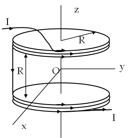
Two coils of wire of same radius \(R\) and \(N\) turns each are separated by a distance \(R\) equal to the radius of the coils as shown in Figure 36.62. Current \(I\) runs in the coils in the same direction as shown. This arrangement is called the Helmholtz coil and is very useful for generating fairly uniform magnetic field. Let the axis of the coils be the \(z\)-axis with origin at the mid-way point between the coils.
Figure 36.62.
(a) Find the magnetic field on the axis as a function of coordinate \(z\text{.}\) (b) Show that the magnetic field at the mid-way point is very uniform with both its first and second derivatives zero.
Solution 1. a
We use the magnetic field at the axis of a circular ring. Suppose a ring of radius \(R\) is in the \(xy\)-plane with its center at the origin. Let a current flow in the ring in the counter-clockwise direction as observed from the positive \(z\)-axis side, then the magnetic field at a point on the \(z\)-axis will be
\begin{equation*} \vec B = \dfrac{\mu_0\:I\:R^2}{2}\:\dfrac{1}{\left( R^2 + z^2\right)^{3/2}}\: \hat u_z. \end{equation*}
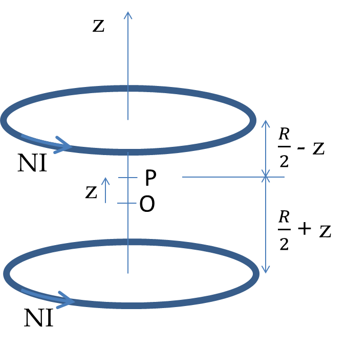
The given structure can be thought to be two rings, each carrying a current equal to \(NI\) for \(N\) rings each. Now, consider a point P between the two rings with the \(z\)-coordinate \(z\text{.}\) Then, the field point has a vertical distance \(\dfrac{R}{2} +z\) from the lower ring and \(\dfrac{R}{2} - z\) from the top ring.
Figure 36.63.
Since the magnetic fields of both rings at P are in the same direction (positive \(z\)-axis direction) we get the following net magnetic field at P.
\begin{equation*} \vec B = \hat u_z \dfrac{\mu_0\:N\:I\:R^2}{2}\:\left\{ \dfrac{1}{\left[ R^2 + \left( \dfrac{R}{2} +z\right)^2\right]^{3/2}} + \dfrac{1}{\left[ R^2 + \left( \dfrac{R}{2} -z\right)^2\right]^{3/2}}\right\}. \end{equation*}
Solution 2. b
By taking derivative of \(\vec B\) with respect to \(z\) and setting \(z=0\) in the result you can show that both the first and second derivatives of the magnetic field near \(z=0\text{,}\) i.e. half-way between the coils is zero.
34. Magnetic Field of a Charged Rotating Disk.
A non-conducting hard rubber circular disk of radius \(R\) is painted with a uniform surface charge density \(\sigma\text{.}\) It is rotated about its axis with angular speed \(\omega\text{.}\) (a) Find the magnetic field produced at a point on the axis a distance \(h\) meter from the center of the disk. (b) Find the numerical value of magnitude of magnetic field when \(\sigma = 1\ \textrm{C/m}^2\text{,}\) \(R = 20\ \textrm{cm}\text{,}\) \(h = 2\ \textrm{cm}\text{,}\) and \(\omega = 400\ \textrm{rad/sec}\text{,}\) and compare it with magnitude of magnetic field of earth which is about \(\frac{1}{2}\) Gauss.
Answer.
(b) \(8.2\times 10^{-7}\times B_{\textrm{Earth}}\text{.}\)
Solution 1. a
We can treat the charged rotating disk as made up of thin rings, each with its own current. Then, the net magnetic field at the field point P on the axis will be obtained from the superposition of the fields of these imagined rings. Since we already know the answer for one ring, this problem becomes a problem of summing over the rings.
Let us look at a ring of radius \(r\) and infintesimal thickness \(dr\text{.}\) Since this an infinitsimal ring we will denote the current in the ring by \(dI\text{.}\)
\begin{equation*} dI = \sigma\:\omega\:r\:dr.\quad (1) \end{equation*}
This expression of the current is obtained by asking: suppose you look at one cross-section of thickness \(dr\) of the ring how much charge will flow past it in unit time. Since the field point P is at a height \(h\) from the ring, the magnetic field there from this ring will be
\begin{equation*} dB_P = \dfrac{\mu_0 \times dI\times r^2}{2}\:\dfrac{1}{(r^2 + h^2)^{3/2}}.\quad (2) \end{equation*}
Using (1) in this expression gives the following expression which is ready for integration.
\begin{equation*} dB_P = \dfrac{\mu_0 \times \sigma\:\omega}{2}\:\dfrac{r^3\:dr}{(r^2 + h^2)^{3/2}}.\quad (3) \end{equation*}
Integrating this from \(r=0\) to \(r=R\) will add up the contributions of all the rings.
\begin{align*} B_P \amp = \dfrac{\mu_0 \times \sigma\:\omega}{2}\: \int_0^R\:\dfrac{r^3\:dr}{(r^2 + h^2)^{3/2}} \\ \amp = \dfrac{\mu_0 \times \sigma\:\omega}{4}\: \int_0^{R^2}\:\dfrac{u\:du}{(u + h^2)^{3/2}} \\ \amp = \dfrac{\mu_0 \times \sigma\:\omega}{2}\: \left[ \sqrt{R^2 + h^2} - 2\sqrt{h^2} + \dfrac{h^2}{\sqrt{R^2 + h^2}} \right] \end{align*}
Solution 2. b
A student is encourage to put in the numerical values given and answer this part. Beware of the units!
35. Magnetic Field of Ring of Current.
Use the magnetic field for a ring of current \(I\) at the axis. (a) Integrate the result from \(z = -\infty\) to \(z=+\infty\) to show that the integral is equal to \(\mu_0 I\text{.}\) (b) Give reasons why this result is expected based on Ampere’s law.
Solution 1. a
We have
\begin{equation*} B_z(z) = \dfrac{\mu_0 I R^2}{2}\:\dfrac{1}{(R^2 + z^2)^{3/2}}. \end{equation*}
Integrating this is done as follows.
\begin{align*} \int_{-\infty}^{\infty}\:B_z(z)\:dz \amp = \dfrac{\mu_0 I R^2}{2}\:\int_{-\infty}^{\infty}\dfrac{dz}{(R^2 + z^2)^{3/2}}\\ \amp = \dfrac{\mu_0 I R^2}{2}\times 2\:\int_{0}^{\infty}\dfrac{dz}{(R^2 + z^2)^{3/2}} \\ \amp = \mu_0 I R^2\:\left[\left.\dfrac{1}{R^2}\:\dfrac{z}{\sqrt{R^2 + z^2}}\right|_{0}^{\infty} \right] = \mu_0\: I [1-0] = \mu_0\: I. \end{align*}
Solution 2. b
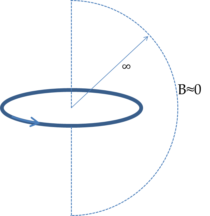
The Amperian loop shown by the dashed line here. The integral of \(\vec B\) over the semi-circular part gives zero since the \(B(r)\) woiuld drop faster than \(1/r\) for large \(r\) as you can see from the formula for \(B(z)\) on the axis. When \(z \gg R\text{,}\) \(B\sim 1/z^3\text{.}\) On the semicircular part, let \(r=R\) and assume the largest value of \(B(r)\) to be \(\bar B\text{,}\) which will be less than \(k/R^3\) for some constant \(k\text{.}\)
Figure 36.64.
Then the integral of \(\vec B\cdot d\vec l\) on the semi-circular part will be less than \(\bar B\times 2\pi R\text{,}\) which will be less than \(2\pi k/R^2\text{.}\) As \(R\rightarrow\infty\) this contribution becomes zero. Therefore
\begin{align*} \amp \oint \: \vec B\cdot d\vec l = \mu_0\:I_{\textrm{enc}},\ \ \Longrightarrow\ \ \int_{-\infty}^{\infty}\:B_z(z)\:dz = \mu_0\:I. \end{align*}
36. Magnetic Field of Two Parallel Wires Carrying Current in Opposite Directions.
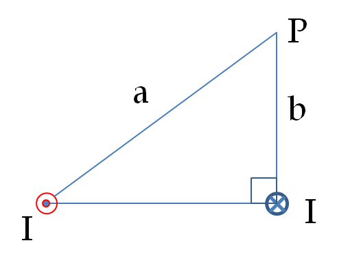
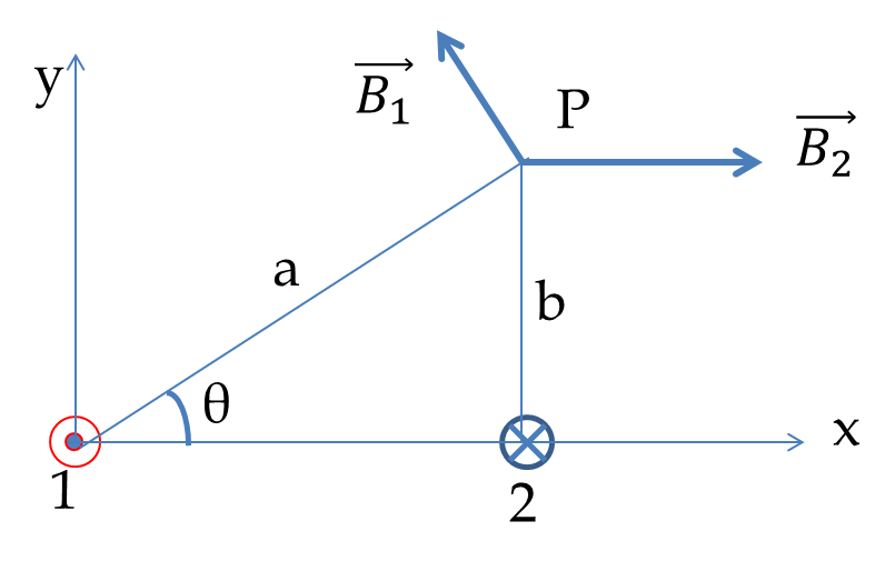
A circuit with current \(I\) has a two long parallel wire sections that carry current in the opposite directions. Find magnetic field at a point P near these wires that is a distance \(a\) from one wire and \(b\) from the other wire as shown in Figure 36.65.
Figure 36.65.
Solution.
In Figure 36.66 each wire will generate a magnetic field that will circulate around that wire.
The field point is at a distance \(a\) from wire 1 and \(b\) from wire 2. Therefore, the magnitudes of the magnetic fields by the two wire at point P will be
\begin{align*} B_1 \amp = \dfrac{\mu_0\:I}{2\pi}\:\dfrac{1}{a},\\ B_2 \amp = \dfrac{\mu_0\:I}{2\pi}\:\dfrac{1}{b}. \end{align*}
Figure 36.66.
At the field point P the directions of the magnetic fields are as indicated in the figure. We need to add the two magnetic field vectors to obtain the actual magnetic field at point P. We do the addition analytically by using the coordinates in the figure. The \(x\)- and \(y\)-components of \(\vec B_1\) and \(\vec B_2\) are
\begin{align*} \amp B_{1x} = -B_1\:\sin\theta,\ \ B_{1y} = B_1\:\cos\theta,\\ \amp B_{2x} = B_2,\ \ B_{2y} = 0. \end{align*}
Therefore, the net magnetic field \(\vec B\) has the following components.
\begin{equation*} B_{x} = -B_1\:\sin\theta + B_2,\ \ B_{y} = B_1\cos\theta. \end{equation*}
From these components we obtain the magnitude of the net magnetic field at P to be
\begin{equation*} B = \sqrt{B_x^2 + B_y^2} = \sqrt{B_1^2 + B_2^2 - 2 B_1 B_2\: \sin\theta}, \end{equation*}
and the direction of the field with respect to the \(x\)-axis is given by the angle \(\phi\)
\begin{equation*} \tan\phi = \dfrac{B_y}{B_x} = \dfrac{B_1\cos\theta}{-B_1\:\sin\theta + B_2}. \end{equation*}
If \(B_2 \gt B_1\sin\theta\text{,}\) the angle will be in the first quadrant and if \(B_2 \lt B_1\sin\theta\text{,}\) the angle will be in the second quadrant.
37. Magnetic Field of a Current in Solid Cylidrical Wire with Varying Current Denssity.
A very long thick cylindrical wire of radius \(R\) carries a current density \(J\) that varies across its cross-section. Magnitude of the current density at a point a distance \(r\) from the center of the wire is given by the following.
\begin{equation*} J= J_0 \frac{r}{R}, \end{equation*}
where \(J_0\) is a constant. Find magnetic field (a) at a point outside the wire and (b) at a point inside the wire. Write your answer in terms of the net current \(I\) through the wire.
Solution 1. a
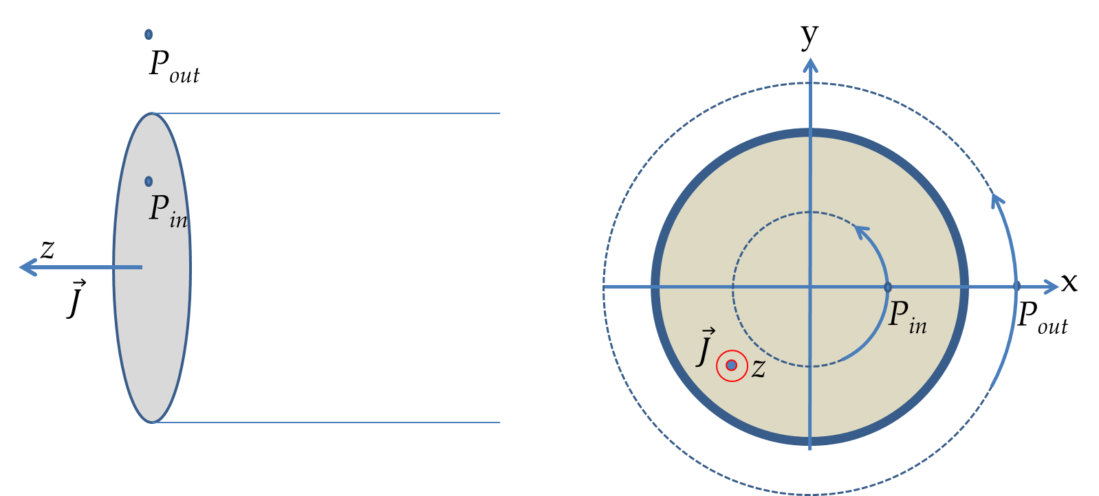
Figure 36.67 below shows a cross-section of the cylindrical wire and the choice of Amperian loops to determine the magnetic fields at a point (\(\text{P}_{\textrm{in}}\)) inside the conductor and a point (\(\text{P}_{\textrm{out}}\)) outside the conductor.
Figure 36.67.
Let \(r\) be the distance from teh axis of the wire to the outside point \(\text{P}_{\textrm{out}}\text{.}\) From the cylindrical symmetry we will get the following for the magnitude of the magnetic field outside the wire,
\begin{align*} 2\pi r\: B_{\textrm{out}} \amp = \mu_0\: I_{\textrm{tot}}, \\ \amp = \mu_0\:\int_0^R\: \left( J_0\:\dfrac{r}{R}\right) \times 2\pi\:r\:dr = \dfrac{2\pi}{3}\:\mu_0\:J_0\: R^2. \end{align*}
Therefore,
\begin{equation*} B_{\textrm{out}} = \dfrac{\mu_0\:J_0\: R^2}{3}\:\dfrac{1}{r}.\ \ \ (r \gt R) \end{equation*}
Solution 2. b
Since the Amperian loop passing through an inside point does not include all the current, we get a different expression for the magnetic field. Let \(B_{in}\) denote the magnetic field at the inside point \(\text{P}_{\textrm{in}}\) and denote the distance to \(\text{P}_{\textrm{in}}\) from the axis by the letter \(r\text{.}\) When we apply Ampere’s law for the loop through the point \(\text{P}_{\textrm{in}}\) we find
\begin{align*} 2\pi r\: B_{\textrm{in}} \amp = \mu_0\: I_{\textrm{enc}}, \\ \amp = \mu_0\:\int_0^r\: \left( J_0\:\dfrac{r}{R}\right) \times 2\pi\:r\:dr = \dfrac{2\pi}{3}\:\mu_0\:J_0\: \dfrac{r^3}{R}. \end{align*}
Therefore,
\begin{equation*} B_{\textrm{in}} = \dfrac{ \mu_0\:J_0}{3 R}\:r^2.\ \ \ (r \lt R) \end{equation*}
38. Magnetic Field of a Current in a Cylindrical Wire with Cavity.
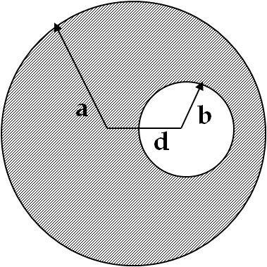
A very long cylindrical wire of radius \(a\) has a circular hole of radius \(b\) in it at a distance \(d\) from the center as shown in Figure 36.68.
The wire carries a uniform current of magnitude \(I\) through it. The direction of the current in the figure is out of the paper. Find magnetic field (a) at a point at the edge of the hole closest to the center of the thick wire, (b) at an arbitrary point inside the hole and (c) at an arbitrary point outside the wire.
Figure 36.68.
Hint.
Think of the hole as a sum of two wires carrying current in the opposite directions.
Solution 1. a
We will use a trick here. We will fill the hole with equal and oppositely fictitious currents so that on net they will not change the magnetic field anywhere. However, when we add the fictitious current in the hole that is in the same direction as the current in the given wire, then we get a current which has a cylindrical symmetry and we can apply Ampere’s law to obtain the magnetic field of this new current. We will call this magnetic field \(\vec B_1\text{.}\)
The oppositely directed fictitious current by itself also has a cylindrical symmetry. Let us call the magnetic field of this fictitious current \(\vec B_2\text{.}\) The vector sum of \(\vec B_1\) and \(\vec B_2\) will get rid of the equal and opposite contributions of the fictitious currents and give us the magnetic field of the current with the hole.
Figure 36.69.
To solve for the magnetic field at \(\text{P}_a\) we will need to evaluate the current enclosed within the Amperian loop in the shape of a circle passing through \(\text{P}_a\) with the center either at the full current or the oppositely-directed fictitious current. Therefore, we will need the current density, which has the magnitude
\begin{equation*} J = \dfrac{I}{\pi\left(a^2 - b^2\right)} \end{equation*}
The radius of the Amperian loop for the entire wire is \(d-b\text{.}\) Therefore, Ampere’s law gives the following for \(B_1\text{:}\)
\begin{equation*} B_1\times 2\pi(d-b) = \mu_0\: I_{\textrm{enc}} = \mu_0\:\pi(d-b)^2\:J. \end{equation*}
Therefore,
\begin{equation*} B_1 = \dfrac{1}{2}\mu_0\:J\:(d-b). \end{equation*}
The direction of this field at point \(\text{P}_a\) is pointed towards the positive \(y\)-axis in the figure.
The radius of the Amperian loop for the oppositely directed fictitious current is \(b\text{,}\) the radius of the hole. Since the point \(\text{P}_a\) is outside of this current, we get the following for \(B_2\text{.}\)
\begin{equation*} B_2\times 2\pi b = \mu_0\: I_{\textrm{enc}} = \mu_0\:\pi b^2\:J \end{equation*}
Therefore,
\begin{equation*} B_2 = \dfrac{1}{2}\mu_0\:J\:b. \end{equation*}
The direction of this field at point \(\text{P}_a\) is pointed towards the negative \(y\)-axis in the figure.
Since the two magnetic fields at \(\text{P}_a\) are in the opposite directions the net magnetic field will be
\begin{equation*} \vec B_{P_a} = B_1\:\hat u_y - B_1\:\hat u_y = \left[ \dfrac{1}{2}\mu_0\:J\:d - \mu_0\:J\:b\right]\:\hat u_y. \end{equation*}
Solution 2. b
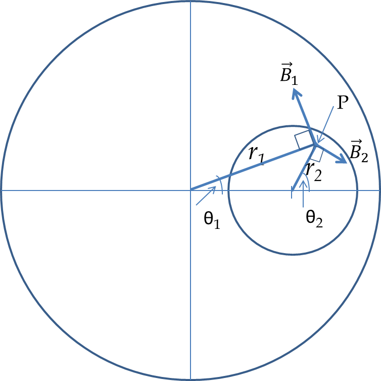
Let \(\text{P}(x,y)\) be an arbitrary point inside the hole. Let \(r_1\) and \(r_2\) be the distance to P from the centers of the two currents we have discussed above. Then, the distance of this point from the centers of the two wire would be
\begin{align*} \amp r_1 = \sqrt{x^2 + y^2},\quad\quad\quad (1a)\\ \amp r_2 = \sqrt{(x-d)^2 + y^2}. \quad (1b) \end{align*}
Figure 36.70.
By following the arguments of the Amepere’s as done in part (a) above we csn show that the magnitude of the magnetic field by the two currents will be
\begin{equation*} B_1 = \dfrac{\mu_0 J r_1}{2},\ \ B_1 = \dfrac{\mu_0 J r_2}{2}, \end{equation*}
and the directions can be obtained by the fact that they are tangential to the respective circles in which the magnetic fields circulate around the corresponding current. The direction of \(\vec B_1\) will be in the direction of the unit vector \(\hat u_1\) given by
\begin{equation*} \hat u_1 = -\sin\theta_1\:\hat u_x + \cos\theta_1\:\hat u_y. \end{equation*}
Similarly, the direction of \(\vec B_2\) will be in the direction of the unit vector \(\hat u_2\) given by
\begin{equation*} \hat u_2 = \sin\theta_2\:\hat u_x - \cos\theta_2\:\hat u_y. \end{equation*}
Therefore, the net \(\vec B\) will be
\begin{equation*} \vec B = \left( -B_1\:\sin\theta_1 + B_2\:\sin\theta_2\right)\:\hat u_x + \left( -B_1\:\cos\theta_1 - B_2\:\cos\theta_2\right)\:\hat u_x \end{equation*}
Solution 3. c
The magnetic field at an arbitrary point with coordinates \((x,y)\) outside the wire is obtained similar to part (b), except, now the \(B_1\) and \(B_2\) will have different expressions since all currents will be enclosed now.
\begin{equation*} \vec B_{\textrm{out}} = \left( -B_1\:\sin\theta_1 + B_2\:\sin\theta_2\right)\:\hat u_x + \left( -B_1\:\cos\theta_1 - B_2\:\cos\theta_2\right)\:\hat u_y, \end{equation*}
with
\begin{equation*} B_1 = \dfrac{\mu_0\:J\:a^2}{2 r_1},\ \ B_1 = \dfrac{\mu_0\:J\:b^2}{2 r_2}, \end{equation*}
where \(r_1\) and \(r_2\) is given by the same formulas as in (1).
39. Magnetic Field of Current in Wire Wound on a Taurus.
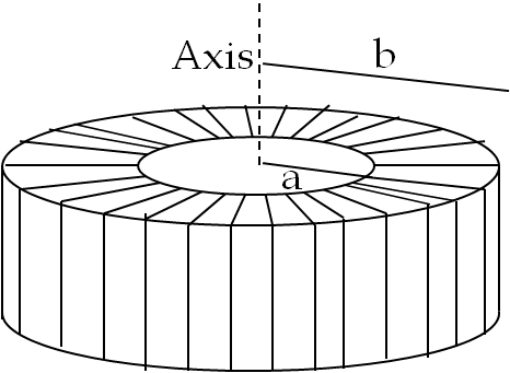
Consider a torus of rectangular cross-section with inner radius \(a\) and outer radius \(b\) as in Figure 36.71. N turns of an insulated thin wire is wound evenly on the torus tightly all around the torus and connected to a battery producing a steady current \(I\) in the wire.
Assume that the current on the top and bottom surfaces in the figure are radial and that the current on the inner and outer radii surfaces is vertical. Find magnetic field inside the torus as a function of radial distance \(r\) from the axis.
Figure 36.71.
Answer.
Magnitude \(\frac{\mu_0}{2\pi}\frac{NI}{r}\text{.}\)
Solution.
Note the magnetic field inside the torus is tangential and circulates in closed loops. For the Amperian loop, imagine a circular loop of radius \(r\) from the center with \(a \lt r \lt b\text{.}\) Let \(B\) be the magnitude of the magnetic field. The circulation of the magnetic field on the loop will be \(B\times 2\pi r\text{.}\) Using this in the Ampere’s law we get
\begin{equation*} B\times 2\pi r = \mu_0\:N\:I,\ \ \Longrightarrow\ \ B = \dfrac{\mu_0\:N\:I}{2\pi}\:\dfrac{1}{r}, \end{equation*}
and the direction is tangential.
40. Magnetic Field of Rotating Charged Cylindrical Caapacitor.
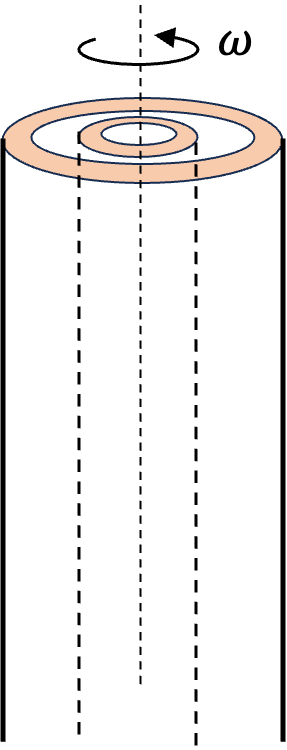
Two long coaxial copper tubes, each of length \(L\text{,}\) are connected to a battery of voltage \(V\text{.}\) The inner tube has inner radius \(a\) and outer radius \(b\text{,}\) and the outer tube has inner radius \(c\) and outer radius \(d\text{.}\) The tubes are then disconnected and rotated in the same direction at angular speed of \(\omega\) radians per second about their common axis as shown in Figure 36.72. Find magnetic field (a) at a point inside the space enclosed by the inner tube \(r \lt a\text{,}\) (b) at a point between the tubes \(b \lt r \lt c\text{,}\) and (c) at a point outside the tubes \(r \gt d\text{.}\)
Figure 36.72.
Hint.
Think of copper tubes as a capacitor and find the charge density on them based on the voltage applied.
Solution.
Let \(r\) be the distance from the axis of the cylinders. Note that outer surface \((r = b)\) on the inner conductor and the inner surface \((r = c)\) of the outer conductor will become charged. The amount of charge \(Q\) depends on the the capacitance \(C\) of the two cylindrical capacitor and the voltage \(V\text{.}\)
\begin{equation*} Q = CV, \ \ C = \dfrac{2\pi\epsilon_0 L}{\ln(c/b)},\ \ \ \ (1) \end{equation*}
where \(L\) is the length of the tubes. The charge \(Q\) is spread over the surface of area \(2\pi b L\) on the inner electrode and over the surface of area \(2\pi c L\) on the outer electrode. Let us make the connections so that inner electrode is positively charged and the outer electrode negatively charged. Let us denote the surface charge densities as \(\sigma_{1}\) and \(\sigma_2\) for inner and outer electrodes respectively.
\begin{equation*} \sigma_1 = \dfrac{Q}{2\pi b L},\ \ \sigma_2 = \dfrac{-Q}{2\pi c L}.\ \ \ \ (2) \end{equation*}
We will leave this expressions in this form. In the final expression below we will use (1) to write these quantities more explicitly and independent of \(L\text{.}\) When we rotate the two electrodes with angular speed \(\omega\text{,}\) the charges on the two surface move at different physical speeds, \(v_1=\omega\:b\) and \(v_2=\omega\:c\text{.}\) Therefore, the surface current densities will be
\begin{equation*} K_1 = \sigma_1\: \omega\:b,\ \ \ K_2 = \sigma_2\: \omega\:c.\ \ \ \ (3) \end{equation*}
Let \(z\)-axis be coincident with the axis of the cylinders. We find that when the two electrodes are spinning the surface currents will generate magnetic fields which are either parallel or antiparallel to the axis of the cylinder. Let \(B_{1z}\) and \(B_{2z}\) be the \(z\)-components of the magnetic fields of the currents on the inner and outer electrodes respectively. An application of Ampere’s law on the inner electrode gives the following for the \(z\)-component of the magnetic field.
\begin{equation*} B_{1z} = \left\{ \begin{array}{ll} \mu_0 K_1,\ \ \ \amp r \lt b,\\ 0,\ \ \ \amp r \gt b, \end{array} \right. \end{equation*}
Similarly,
\begin{equation*} B_{2z} = \left\{ \begin{array}{ll} \mu_0 K_2,\ \ \ \amp r \lt c,\\ 0\:\mu_0 K_1,\ \ \ \amp r \gt c, \end{array} \right. \end{equation*}
Now, with \(B_z = B_{1z} + B_{2z}\text{,}\) we can find the magnetic field in different regions.
\begin{equation*} B_{z} = \left\{ \begin{array}{ll} \mu_0 (K_1+K_2),\ \ \ \amp r \lt a, \\ \mu_0 K_2,\ \ \ \amp b \lt r \lt c, \\ 0,\ \ \ \amp r \gt c, \end{array} \right. \end{equation*}
Replacing \(K_1\) and \(K_2\) from (3), then replacing \(\sigma_1\) and \(\sigma_2\) from (2), and then finally replacing \(Q\) by (1) gives the answers for parts (a), (b) and (c).
\begin{equation*} B_{z} = \left\{ \begin{array}{lll} 0,\ \ \ \amp r \lt a, \quad \amp (a) \\ \dfrac{\mu_0\epsilon_0\omega\:V}{\ln(c/b)},\quad \amp b \lt r \lt c, \quad \amp (b)\\ 0,\ \ \ \amp r \gt c, \quad \amp (c) \end{array} \right. \end{equation*}