Section 34.2 Electromotive Force
What makes a current flow in a metal? The conduction electrons in a metal move at high speeds randomly due to the themal energy as if the metal were a gas of electrons. You might get a sense of the speed of the random motion of electrons by setting kinetic energy to \(\frac{3}{2}k_B T\) where \(k_B\) is the Boltzmann constant and \(T\) the temperture in Kelvin scale. At roome temperature, this gives the speed of the thermal motion of electrons to be \(\sim 10^5\) m/s.
Since the thermal motion is random, overall the same number of electrons go in every direction and there is no net flow along a wire. For electrons to flow predominantly in one direction, we need a force on the electron. When a potential difference exists between the ends of a metal wire, there is also an electric field inside the wire. The conduction electrons would drift in a preferred direction as a result of the electric force due to the electric field.
Suppose, at \(t=0\) a potential difference is created by placing \(+q\) at one end and \(-q\) at the other end of a copper wire as shown in Figure 34.8. When you make the connection at \(t=0\text{,}\) electrons will flow in the wire from the lower potential place (\(-\) end) to the higher potential place (\(+\) end), i.e., in the opposite direction to the electric field in the wire until the charges on the two ends have been neutralized.
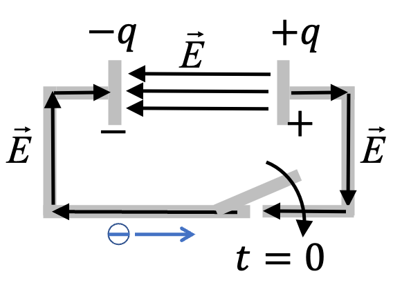
If we wish to maintain the current in the wire then we need a mechanism by which electrons arriving at the \(+\) end are continuously removed and new electrons are placed at the \(-\) end so that the potential difference between the ends could continue to exist.
This task will require work by an agent since it will be moving negatively charged electrons from a higher potential (the \(+\) end) to a lower potential (the \(-\) end) in the space between the plates. After the transfer the electrons would move in the wire from the negative plate to the positive plate guided by the electric field.
That means, for the electron to go around in the circuit, the external agent will need to do work for transfer of electrons between the plates, while the movement outside is handled by the electric field. The amount of energy per unit charge spent by the battery is called the electromotive force (EMF) of the battery. We wil denote EMF by symbol, \(\mathcal{E}\text{.}\)
In a voltaic cell or a battery, the EMF is provided by chemical reactions at the electrodes - electrons are taken away from the positive electrode, called anode and deposited at the negative electrode, called cathode making use of appropriate chemical reactions. An example voltaic cell is illustrated in Figure 34.9.
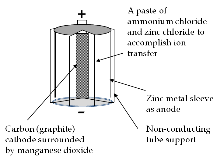
Chemicals that are used up in the process get replenished by the migration of chemicals in the medium between the electrodes. To allow the movement of ions, the mixture in dry cell batteries is kept in the form of an emulsion, while in car batteries, the chemicals are in a liquid mixture. When a battery runs out of chemicals needed for the EMF, it stops functioning.
Since the sources of EMF in a battery are chemical reactions, the electromotive force of a single cell is limited by the energy generated when electrons are transferred from one chemical ion to another. These energies typically lie in the range of 1-3 electron volts, which corresponds to an EMF of 1-3 volt.
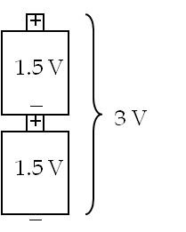
To make batteries of higher voltages you can stack these 1-3 volt cells. Thus, to make a 3-volt battery out of two 1.5-V single voltaic cells, you connect voltaic cells in series, connecting \(+\) terminal of one to the \(-\) terminal of another as shown in Figure 34.10. Higher voltage batteries can be constructed this way.
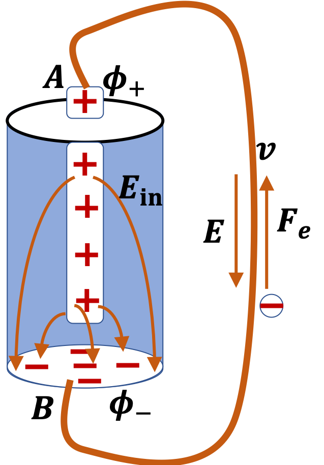
When you trace energy of an electron in a closed circuit, B-A-inside-B, you notice that an electron loses energy \(- e\Delta \phi\) in the wire and gains same amount of energy when electrical energy is used to move an electron from the positive terminal to the negative terminal inside the battery.
The energy of each electron in B-A-inside-B path will first drop by \(-e\Delta \phi\) and then increase by \(e\mathcal{E}_\text{battery}\) ending up same at start.
\begin{equation*}
- e (\phi_+ - \phi_-) + e\mathcal{E}_\text{battery} = 0.
\end{equation*}
Therefore, EMF of a battery is just the potential difference between the terminals, which is also called the voltage of the battery.
\begin{equation}
\mathcal{E}_\text{battery}= \phi_+ - \phi_- = \text{Voltage}.\tag{34.6}
\end{equation}
Subsection 34.2.1 Van der Graaff Generator
A mechanical device called the van de Graff generator, which is often used in physics demonstrations of static electricity, creates a large EMF (see Figure 34.12).
In the van de Graff generator, electrons are transported from a high potential to a low potential by way of a mechanical transport over a non-conducting rubber belt.
Mechanical work is needed because electrons are moved in the direction opposite to how the electrons will move in the prevailing electric field.
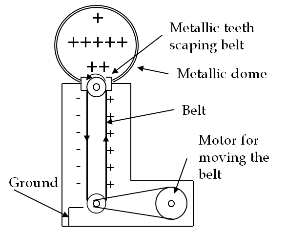
Electrons are stripped off from the rubber belt by high field on the brushes, although at other places electric field is not high enough to slide the electrons on the belt itself. The mechanical motor in the van de Graff generator does work in transporting the charge on the belt.
Subsection 34.2.2 (Calculus) EMF from Electric Field
The amount of energy per unit charge spent by a source of electrical energy is called the electromotive force (EMF) of the source. The EMF is not any force in the mechanical force sense; rather, it is related to the energy. Let’s look at change in energy of an electron as it is moved from the positive terminal to the negative terminal outside an EMF source.
Let us calculate EMF of a battery as in Figure 34.11 by figuring out work required to move an electron from the positive terminal to the negative terminal in the inside of the battery. Note that electric field is in the same direction as this displacement, so you would need to do balance the electric force, and hence you will do some work. This work is done by chemical reactions inside the battery. We denote this fictitious force by \(\vec{F_\text{ch}}\) and assume it balances the electric force inside the battery. Therefore, work will be
\begin{align*}
W_{+\rightarrow -} \amp = \int_{+}^{-} \vec{F_\text{ch}}\cdot d\vec r\\
\amp = e\int_{+}^{-} \vec E_\text{in}\cdot d\vec r
\end{align*}
Dividing this work by \(e\) gives EMF of the battery in terms of electric field inside the battery.
\begin{equation}
\mathcal{E}_\text{battery} = \int_{+}^{-} \vec E_\text{in}\cdot d\vec r .\tag{34.7}
\end{equation}
This equation is of just theoretical interest since we do not know electric field inside the battery. If you assume electric field to be constant, then you can get a sense of electric field by the distance between the electrodes. Let \(d\) be the distance between electrodes. Then, roughly, we will get
\begin{equation*}
\mathcal{E}_\text{battery} = E_\text{in}\; d.
\end{equation*}
Since \(\mathcal{E}_\text{battery}\) is equal to the voltage of the battery, this equation can give us a sense of the magnitude of electric field inside a battery.
